Reference pages
The Reference tab of each item shows the pages it lists. These are all of them.
AC and DC in a panel
DC (direct current) flows one way, at a steady voltage, from + to − (common, 0 V).
AC (alternating current) reverses direction many times a second. Its frequency is in hertz (Hz): 60 Hz in the United States, 50 Hz in much of the world. A transformer steps AC voltage up or down.
| Power | Typical use | Comes from |
|---|---|---|
| 480 V AC, three-phase (L1, L2, L3) | Motors, heaters | The building's supply, through the main disconnect |
| 120 V AC, single-phase | Contactor and relay coils, lights, the DC supply | A control transformer |
| 24 V DC | PLC inputs and outputs, sensors, pilot lights | A DC power supply |
The PLC switches a contactor's coil; the contactor's main contacts switch the motor.
Wire I/O only to the power it is made for. A 24 V DC input card on 120 V AC can be destroyed.
| On a motor nameplate | Means |
|---|---|
| V | The voltage it is wound for (460 V runs on a 480 V supply) |
| Ph | Phases: 1 or 3 |
| Hz | Frequency: 60 |
| FLA | Full-load amps: the current at full load |
| HP, RPM | Power and speed |
Arrays
An array is one tag that holds a numbered list of values of one type.
| IEC (PLC+) | Allen-Bradley Logix | |
|---|---|---|
| Declare | FillTime : ARRAY[1..4] OF TIME |
FillTime of type DINT[4] |
| Numbered | from the first number you choose (here 1 to 4) | always from 0 (here 0 to 3) |
| One element | FillTime[3] |
FillTime[3] |
| Index from a tag | FillTime[Recipe] |
FillTime[Recipe] |
- An element works anywhere a tag of its type works.
- In PLC+, elements start at 0: fill a table with MOVEs.
- An index outside the array stops the PLC with an index-out-of-range fault (a major fault on a Logix controller). Check it first: GE Recipe 1 and LE Recipe 4 in front of the MOVE (or LIM on Allen-Bradley).
- Give a timer a checked copy (FillPT), not FillTime[Recipe]: a timer reads its PT on every scan, even when its rung is off.
- In PLC+ an array is declared in the program's tags; this module's exercise gives it to you in the program it starts with.
BCD (binary-coded decimal)
Each decimal digit gets its own four bits, holding 0 to 9.
| Digit | BCD | Digit | BCD |
|---|---|---|---|
| 0 | 0000 | 5 | 0101 |
| 1 | 0001 | 6 | 0110 |
| 2 | 0010 | 7 | 0111 |
| 3 | 0011 | 8 | 1000 |
| 4 | 0100 | 9 | 1001 |
- Decimal to BCD: write each digit as four bits, in order. 406 → 0100 0000 0110.
- BCD to decimal: groups of four from the right, one digit each. 0111 0011 1001 → 739.
- Never valid: 1010, 1011, 1100, 1101, 1110, 1111 (10 to 15). Finding one means a fault.
- Seen in hex, a BCD word shows its decimal digits: BCD 25 is
16#25. - Read as plain binary by mistake, BCD 0010 0101 (25) becomes 37. Convert first.
- Range: 16 bits hold 0 to 9,999 in BCD, but 0 to 65,535 in binary.
| Device | PLC points |
|---|---|
| Thumbwheel switch | 4 inputs per digit (worth 1, 2, 4, 8) |
| 7-segment display with a BCD decoder | 4 outputs per digit |
| Convert | Allen-Bradley | IEC 61131-3 |
|---|---|---|
| BCD to a number | FRD | BCD_TO_INT |
| A number to BCD | TOD | INT_TO_BCD |
Boolean logic
TRUE = 1 = on. FALSE = 0 = off.
| A | B | A AND B | A OR B | A XOR B | NOT A |
|---|---|---|---|---|---|
| FALSE | FALSE | FALSE | FALSE | FALSE | TRUE |
| FALSE | TRUE | FALSE | TRUE | TRUE | TRUE |
| TRUE | FALSE | FALSE | TRUE | TRUE | FALSE |
| TRUE | TRUE | TRUE | TRUE | FALSE | FALSE |
| Operation | TRUE when | Textbook | In ladder |
|---|---|---|---|
| AND | every input is TRUE | A · B | contacts in series |
| OR | any input is TRUE | A + B | contacts in parallel |
| NOT | its input is FALSE | Ā or A′ | a normally closed contact -|/|- (XIO) |
| XOR | the two inputs differ | A ⊕ B | two branches in parallel: A with NOT B, and NOT A with B |
Order of operations:
- Brackets
- NOT (only the input or bracket just after it)
- AND
- XOR
- OR
A OR B AND C means A OR (B AND C). When in doubt, write the brackets.
Rows: n inputs make 2ⁿ rows (2, 4, 8, 16). List them in counting order, all FALSE first.
Sentence to expression: name each condition as a tag; "and" is AND, "or" is OR, "not" and "unless" are NOT (unless X = AND NOT X); bracket each idea that belongs together.
Cascading timers and counters
One timer's or counter's output drives another's input, or resets one.
| Pattern | How |
|---|---|
| A flasher | T1 on NOT T2.Q times the on part; T2 on T1.Q times the off part; the light is on while NOT T1.Q. T2 done resets T1, which resets T2 |
| A chain of times | each TON starts on the one before it being done; the last one done resets the first (the traffic light) |
| Count of a timer | a timer that restarts itself every minute, counted by a CTU with PV 60: an hour |
| Count of a count | C1 counts items (PV 6) and is reset by its own Q; C2 counts C1.Q (PV 4) |
| Reset from two places | R takes one tag: make a memory tag from a branch, such as PackReset = C1.Q OR CaseRemoved |
- A counter reset by its own Q makes a one-scan pulse each time it finishes: exactly one count for the next counter.
- Rung order matters by one scan: a contact above a box reads the box's value from the last scan, one below it from this scan. If a cascade misbehaves, Pause and Step one scan.
- Allen-Bradley: the same with .DN (XIO T2.DN on T1's rung; XIC Bottles.DN then RES Bottles on its own rung).
Coils
| Symbol | Name | What it does to its tag | Allen-Bradley |
|---|---|---|---|
-( )- |
Coil | TRUE while power reaches it, FALSE when not | OTE |
-(/)- |
Negated coil | the opposite | (none) |
-(S)- |
Set (latch) | power turns it on, and it stays on | OTL |
-(R)- |
Reset (unlatch) | power turns it off | OTU |
Use one normal coil per tag. Two normal coils for the same tag fight: the last rung wins, and PLC+ warns you.
Compare
A compare box passes power on when power reaches it and its comparison is true. IN1 and IN2 are tags or typed numbers.
| IEC | Allen-Bradley | True when |
|---|---|---|
| EQ | EQU | IN1 = IN2 |
| NE | NEQ | IN1 ≠ IN2 |
| GT | GRT | IN1 > IN2 |
| GE | GEQ | IN1 ≥ IN2 |
| LT | LES | IN1 < IN2 |
| LE | LEQ | IN1 ≤ IN2 |
- In series: AND. GE X 1 then LE X 4 is true for 1 to 4 (a range). Allen-Bradley's LIM tests a range in one box.
- In parallel: OR. LT X 1 beside GT X 4 is true outside 1 to 4.
- A target reached: use GE, not EQ (EQ misses a count that goes past).
- "3 or fewer" is LE 3; "fewer than 3" is LT 3.
- A counter's count is C1.CV (.ACC on Allen-Bradley); a timer's time so far is T1.ET.
Contacts
| Symbol | Name | Passes power when | Allen-Bradley |
|---|---|---|---|
-| |- |
Normally open | its tag is TRUE | XIC |
-|/|- |
Normally closed | its tag is FALSE | XIO |
-|P|- |
Rising edge | for one scan, when its tag turns TRUE | XIC + ONS |
-|N|- |
Falling edge | for one scan, when its tag turns FALSE | XIO + ONS |
A contact reads a tag; it never changes it. In PLC+ the editor keys are O (open), C (closed), P and N.
Counters
A counter counts edges: its count changes once each time its input turns from FALSE to TRUE, however long the input stays on.
| Box | Counts | Q | Other inputs |
|---|---|---|---|
| CTU | up, on the rung's power (CU) | TRUE while CV is at least PV | R: count to 0 |
| CTD | down, on the rung's power (CD) | TRUE while CV is 0 or less | LD: count to PV |
| CTUD | up on the rung, down on its CD input | QU: CV at least PV; QD: CV 0 or less | R: to 0; LD: to PV |
- PV is the preset value; CV the count so far (an INT). A counter named C1 has C1.Q (or C1.QU, C1.QD) and C1.CV.
- A counter does not stop at PV: it keeps counting, and Q stays on.
- A counter keeps its count through a stop; only R (or LD) changes it.
- To show CV on a display: a MOVE box, IN C1.CV, OUT the display's tag.
Allen-Bradley
| IEC (PLC+) | Allen-Bradley |
|---|---|
| PV | .PRE |
| CV | .ACC |
| Q | .DN (TRUE while .ACC is at least .PRE, for CTU and CTD) |
| R | a RES instruction on its own rung, naming the counter tag |
| CTUD | a CTU and a CTD on two rungs naming the same counter tag |
.OV and .UN show that the count went over or under its range.
Data types
| Type | Holds | Size | Use it for |
|---|---|---|---|
| BOOL | TRUE or FALSE | 1 bit | buttons, sensors, lights, valves |
| INT | −32,768 to 32,767 | 16 bits | counts, thumbwheels, displays |
| DINT | about −2.1 billion to 2.1 billion | 32 bits | large counts and totals |
| REAL | numbers with a decimal point (72.5) | 32 bits | temperatures, flows, averages |
| TIME | a length of time (T#5s, T#500ms) | timer presets (IEC) |
- Choose the smallest type that always fits.
- A whole number too big for its type wraps round (INT: 32,767 + 1 = −32,768).
- REAL into INT is rounded to the nearest whole number (exactly .5 goes to the even one: 2.5 → 2).
- IEC asks for conversions to be written (REAL_TO_INT, INT_TO_REAL…); in PLC+ and on Allen-Bradley, MOV and math convert to the destination's type by themselves.
- Allen-Bradley Logix: BOOL, SINT (8 bits), INT, DINT, LINT (64 bits), REAL. DINT is the usual whole number. No TIME type: a timer's preset (.PRE) and time (.ACC) are DINT milliseconds.
- In PLC+, a new tag typed in a box is declared for you: a TIME in a timer's PT, a BOOL on a contact, a coil or a box's R, an INT anywhere else.
Diagnostic tools
| In PLC+ | What it shows or does | On an Allen-Bradley PLC |
|---|---|---|
| Live values on the rungs | each tag's value; a contact or coil with power is green and thick | online monitoring in Logix Designer: true instructions highlighted |
| What every part is doing | each part's real state, in words | the machine itself; a sensor's own light |
| The wiring: which tag is which | every I/O tag and what it means | the I/O list and the wiring drawings |
| Pause / Run, Step one scan | stop the clock; run one 10 ms scan | not on a running machine (a real process does not pause) |
| keep pressed | holds a push button down while you step | |
| Force Tag ON / OFF (right-click a contact or coil) | the PLC uses that value whatever the machine does; FORCED shows on the rung | I/O forcing; the controller's FORCE light is on while forces are enabled |
| Remove the force / Reset | the tag follows the machine again; Reset removes every force | remove and disable forces |
| Problems | what stops the program running (a missing tag, a wrong type) | Verify (errors and warnings) |
| Check my program, Replay the failed test | the task's tests; a failed test replayed on the machine | (your own test plan) |
| every rung that uses a tag | Cross Reference | |
| a tag's value over time | Trends |
- An input module's lights show each input at its terminal; an output module's lights show each output the PLC is driving.
- A force bypasses what the program checks. Force only with permission, with everyone clear, and remove it when you are done.
Edges (one-shots)
- A rising edge passes power for exactly one scan when its tag goes from FALSE to TRUE.
- A falling edge passes power for exactly one scan when its tag goes from TRUE to FALSE.
- Use an edge to do something once per event: count a part, reset a memory when a part has passed, toggle a mode.
- Allen-Bradley: ONS (one-shot) after the contact, or OSR/OSF.
Kinds of fault
| Fault | What the PLC sees or does | How it shows | How to confirm |
|---|---|---|---|
| Broken wire to an input (open) | always FALSE | its contact never changes | force it ON: the machine works |
| Short on an input | always TRUE | its contact is TRUE with nothing there | the device's own light is off; meter |
| Two input wires crossed | the input follows another device | its contact changes when another device is worked | work each device in turn |
| Sensor stuck on or off | always TRUE or always FALSE | the same as a short or a broken wire | the sensor's own light; swap or test the sensor |
| Failed output device (motor, valve, lamp, cylinder) | the PLC turns the output on | coil TRUE, the device does nothing | force the output ON: still nothing |
| Program bug | inputs right, output wrong | the rung does not do what the task says | read the rung; step one scan |
- A normally closed Stop with a broken wire reads like a press: the machine stops or will not start. It fails safe. A short on it means Stop no longer stops: that is why an emergency stop is also wired into the power circuit.
- A failed device often shows up as something else that did not happen: a tank that never fills, a sequence that waits for a sensor for ever.
- An output's tag being TRUE does not prove the device works.
Interlocks and limit switches
- Interlock: each of two outputs that must never be on together has a normally closed contact of the other in its rung. Whichever starts first locks the other out.
- Limit switch: a switch worked by the moving part at the end of its travel. A normally closed contact of it in the direction's rung stops the motion at the limit.
- In a real panel the interlock is also wired between the contactors, and often mechanical too, because a welded contact could defeat the program.
Input and output modules
The path of a signal: field device → wire → terminal → input point (numbered from 0) → tag in the program. An output runs the other way.
| Word | Means |
|---|---|
| Discrete | On or off: TRUE or FALSE |
| Analog | A range of values (module 9) |
| Sourcing | Supplies current: switches +24 V out (PNP sensors) |
| Sinking | Takes current in and leads it to 0 V (NPN sensors) |
One side sources, the other sinks: a PNP (sourcing) sensor needs a sinking input; an NPN (sinking) sensor needs a sourcing input. Check the module's wiring diagram.
| Output | Switches | Notes |
|---|---|---|
| Relay | AC or DC | Slow; contacts wear |
| Transistor | DC only | Fast; sinking or sourcing |
| Triac | AC only | Small leakage when off |
- An output point carries a small current, so it drives a contactor coil, and the contactor switches the motor.
- Input LED lit: voltage at the terminal. Output LED lit: the PLC has told the point to turn on, not proof the device has power.
- Match the voltage: a 24 V DC module for 24 V DC devices, a 120 V AC module for 120 V AC devices.
Reading a ladder diagram
- The left rail is power; the right rail is the return.
- Each rung is one circuit, read left to right: contacts, then a coil at the right-hand end.
- Contacts in series (one after the other) = AND. Contacts in parallel (a branch) = OR.
- A PLC runs the rungs top to bottom, once per scan.
- In PLC+, a part that passes power is drawn green and thick and says TRUE; one that does not is grey and thin and says FALSE.
Lockout/tagout
An introduction only. It does not replace the safety training your lab or employer gives you, and it does not qualify you to work on live equipment. Follow their written procedure every time.
The rules: OSHA 29 CFR 1910.147, The control of hazardous energy (lockout/tagout); NFPA 70E, Standard for Electrical Safety in the Workplace.
- Prepare and notify: know every energy source; tell everyone affected.
- Shut down with the machine's normal controls.
- Isolate every energy source (disconnect, valves).
- Apply your own lock and tag. You keep the only key.
- Release or block stored energy: air, hydraulics, springs, raised parts, capacitors.
- Verify zero energy: try the Start with everyone clear, then return it to off; test for voltage live-dead-live (meter on a known live source, the circuit, the live source again).
Not a lockout: an emergency stop, a stopped PLC program, a pressed Stop button, or a tag with no lock where a lock fits.
Live work: only if you are qualified, trained for the task, permitted, and wearing the protective equipment it calls for.
Math
While power reaches it, a math box works out IN1 and IN2 and writes the answer to OUT (a tag), on every scan. It passes power on, so boxes in series run left to right.
| IEC | Allen-Bradley | OUT |
|---|---|---|
| ADD | ADD | IN1 + IN2 |
| SUB | SUB | IN1 − IN2 |
| MUL | MUL | IN1 × IN2 |
| DIV | DIV | IN1 ÷ IN2 |
| MOD | MOD | the remainder of IN1 ÷ IN2 |
- Whole numbers drop the remainder: 50 DIV 12 = 4, 50 MOD 12 = 2, 2 DIV 3 = 0. For a percentage, multiply first:
part × 100 ÷ total. - Divide by zero: in PLC+, DIV or MOD by 0 stops the PLC with a math fault (outputs off; Reset to restart). Check first: GT X 0 in front of the DIV.
- Overflow: an INT holds −32,768 to 32,767. A bigger result wraps round: 32,767 + 1 = −32,768. Use a DINT for large numbers.
- Counting with ADD: a rising-edge contact (-|P|-) in front, or it adds on every scan.
- Allen-Bradley also has CPT (compute), which works out a whole expression in one box.
MOVE
MOVE (IEC) or MOV (Allen-Bradley): while power reaches it, copies IN (a tag or a number) into OUT (a tag), on every scan. With no power, OUT keeps its last value. It passes power on.
| Job | Rung |
|---|---|
| Set a preset from a recipe | -|/|- RecipeB then MOVE 5 into Target |
| Show a count on a display | MOVE C1.CV into the display's tag |
| Take a snapshot | -| |- AcceptPB then MOVE OrderQty into Accepted |
| Clear a value | -| |- ClearPB then MOVE 0 into Accepted |
- Two MOVEs into one tag with no contacts: both run, and the lower rung wins.
- Writing into another type converts the value: a REAL into an INT is rounded; a number too big for an INT wraps round.
- A numeric display shows only what the program writes to its tag.
- BCD: convert before a BCD display (TOD on Allen-Bradley) and after a BCD thumbwheel (FRD). PLC+ has no BCD instruction yet.
- Allen-Bradley's COP copies a whole block of an array at once.
Number systems
Binary (base 2) uses 0 and 1; each place is worth twice the one to its right. Hexadecimal (base 16) uses 0–9 and A–F; one hex digit is four bits.
| Bit | 15 | 14 | 13 | 12 | 11 | 10 | 9 | 8 |
|---|---|---|---|---|---|---|---|---|
| Worth | 32768 | 16384 | 8192 | 4096 | 2048 | 1024 | 512 | 256 |
| Bit | 7 | 6 | 5 | 4 | 3 | 2 | 1 | 0 |
|---|---|---|---|---|---|---|---|---|
| Worth | 128 | 64 | 32 | 16 | 8 | 4 | 2 | 1 |
| Decimal | Binary | Hex |
|---|---|---|
| 0 | 0000 | 0 |
| 1 | 0001 | 1 |
| 2 | 0010 | 2 |
| 3 | 0011 | 3 |
| 4 | 0100 | 4 |
| 5 | 0101 | 5 |
| 6 | 0110 | 6 |
| 7 | 0111 | 7 |
| 8 | 1000 | 8 |
| 9 | 1001 | 9 |
| 10 | 1010 | A |
| 11 | 1011 | B |
| 12 | 1100 | C |
| 13 | 1101 | D |
| 14 | 1110 | E |
| 15 | 1111 | F |
- Decimal to binary: subtract the largest place value that fits, again and again; or divide by 2 and read the remainders bottom up.
- Binary to hex: groups of four bits from the right, one hex digit each. Hex to binary: four bits per hex digit.
- Hex to decimal: each place is worth 16 times the one to its right: 1, 16, 256, 4096.
| Written as | Means | Also seen as |
|---|---|---|
2#1010 |
binary 1010 = 10 | 1010₂, 0b1010 |
16#FF |
hex FF = 255 | 0xFF, FFh |
10#99 or 99 |
decimal 99 |
| Type | Bits | Holds |
|---|---|---|
| BOOL | 1 | FALSE or TRUE |
| SINT | 8 | −128 to 127 |
| INT | 16 | −32,768 to 32,767 |
| DINT | 32 | about −2.1 billion to 2.1 billion |
A 16-point input module is one 16-bit word: input 0 is bit 0. On the Allen-Bradley PLC, Status.3 is bit 3 of the tag Status.
Ohm's law and power
| Quantity | Symbol | Unit | What it is |
|---|---|---|---|
| Voltage | V | volt (V) | The push, measured between two points |
| Current | I | ampere (A) | The flow through the circuit |
| Resistance | R | ohm (Ω) | How hard a part makes it for current to pass |
| Power | P | watt (W) | How fast energy is used |
Ohm's law: V = I × R, so I = V / R and R = V / I.
Power: P = V × I.
| Prefix | Means | Example |
|---|---|---|
| m (milli) | ÷ 1000 | 50 mA = 0.05 A |
| k (kilo) | × 1000 | 1.2 kΩ = 1200 Ω |
| M (mega) | × 1 000 000 | 1 MΩ = 1 000 000 Ω |
Change to V, A and Ω before you calculate. Example: a 24 V DC coil of 480 Ω draws 24 V / 480 Ω = 0.05 A = 50 mA, and uses 24 V × 0.05 A = 1.2 W.
Open circuit: a break in the path; no current. A PLC input with a broken wire reads FALSE all the time.
Short circuit: a path with almost no resistance; a very large current until a fuse or breaker opens. A shorted switch makes its input read TRUE all the time.
PLC hardware
| Part | What it does |
|---|---|
| Power supply | Turns plant power (often 120 V AC) into the low DC voltage the PLC runs on |
| Processor (CPU, controller) | Runs the program, scan after scan |
| Memory | Holds the program and every tag's value; kept with the power off |
| Input modules | Connect buttons, switches and sensors |
| Output modules | Connect lights, valves and contactor coils |
| Rack (chassis) | Holds the modules in numbered slots |
| Communication ports | Connect the programming PC, a touch screen (HMI), a network |
- Compact (fixed) PLC: power supply, processor and a set number of points in one box. For small machines.
- Modular PLC: separate modules in a rack or row, chosen for the machine. Swap a failed module to repair it.
- Download: copy the program from the PC to the PLC. Upload: from the PLC to the PC. Online: watch it run.
Allen-Bradley examples: Micro800 (compact; Connected Components Workbench), CompactLogix (modular; Studio 5000 Logix Designer), and the older SLC 500 and MicroLogix (RSLogix 500).
Relays and contactors
A relay is a switch worked by an electromagnet (its coil). Energize the coil and all its contacts change over.
| Term | Meaning |
|---|---|
| Coil | The electromagnet. Energized = has voltage across it |
| Normally open (NO) | Open while the coil is off; closes when it is energized |
| Normally closed (NC) | Closed while the coil is off; opens when it is energized |
| Contactor | A heavy-duty relay that switches a motor's current |
| Auxiliary contact | A small extra contact on a contactor, used in the control circuit (the seal-in uses one) |
The scan cycle
A PLC repeats one cycle, over and over:
- Read the inputs: copy every input's state into its tag.
- Run the program: every rung, top to bottom, using those copies.
- Write the outputs: copy the output tags to the real outputs.
- Housekeeping: talk to the programming software and the network, check itself.
So an input that changes in the middle of the program is not seen until the next scan, and a later rung can overwrite what an earlier rung did to the same tag. In PLC+ one scan is 10 ms of simulated time.
- Double coil: two coils of one tag on different rungs. The later rung wins. Use one coil per output.
- Short pulses: an input that turns on and off between two reads is missed.
- Watchdog: a scan that takes too long stops the PLC with a fault.
- Allen-Bradley Logix controllers update their I/O on their own timer (the RPI), not once per scan.
The seal-in (holding) circuit
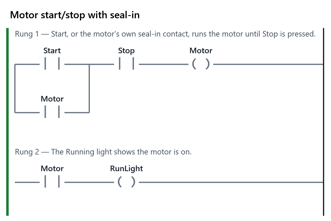
Motor = (Start OR Motor) AND Stop. The Motor's own contact, in parallel with Start, keeps the motor running after Start is let go. Pressing Stop (Stop goes FALSE) breaks the rung.
Truth table: (Start OR Motor) AND Stop
| Start | Motor | Stop | (Start OR Motor) AND Stop |
|---|---|---|---|
| FALSE | FALSE | FALSE | FALSE |
| FALSE | FALSE | TRUE | FALSE |
| FALSE | TRUE | FALSE | FALSE |
| FALSE | TRUE | TRUE | TRUE ✓ |
| TRUE | FALSE | FALSE | FALSE |
| TRUE | FALSE | TRUE | TRUE ✓ |
| TRUE | TRUE | FALSE | FALSE |
| TRUE | TRUE | TRUE | TRUE ✓ |
Sensors
| Sensor | Senses | Its tag is TRUE when |
|---|---|---|
| Limit switch | a moving part touching its lever | the part is there (unless wired normally closed) |
| Float switch | liquid level | the liquid is at or above the float |
| Proximity sensor | metal near its face, without touching | metal is in front of it |
| Photo eye | something breaking a light beam | depends on how it is set up: "beam clear" or "beam blocked". Read the wiring list |
A safety eye is wired so that a failure looks like a blocked beam: the machine stops.
- An inductive prox senses metal only; a capacitive prox senses almost anything.
- Photo eyes: through-beam (sender and receiver apart), retro-reflective (aimed at a reflector), diffuse (bounces off the object). Light operate: on while the beam is clear. Dark operate: on while it is blocked.
- A broken wire reads FALSE, so wire stop and safety signals so that FALSE means stop: they fail safe.
- Switches have two wires; most electronic sensors have three (+24 V, 0 V, output), PNP or NPN to match the input module.
Sequencers with a step number
One INT tag (Step) holds the number of the step: 0 idle, 1, 2, 3, …
| Rung | Shape | Allen-Bradley |
|---|---|---|
| An output | EQ Step n, then the coil | EQU, OTE |
| A move on | EQ Step n, the condition, MOVE n+1 to Step | EQU, XIC, MOV |
| A timed step | EQ Step n, then TON; the next rung uses its .Q | EQU, TON (.DN) |
| Start | EQ Step 0, StartPB, MOVE 1 to Step | |
| Stop (any step) | NOT StopPB, MOVE 0 to Step, with no EQ |
- EQ passes power when IN1 equals IN2. MOVE copies IN to OUT while power reaches it.
- An output on in several steps: one rung, EQ boxes side by side. Two coils of the same tag: the lower rung wins.
- Rungs below a MOVE see the new step in the same scan.
- Numbering 10, 20, 30 leaves room to add steps later.
- Allen-Bradley also has SQO (sequencer output), which steps through a table of output patterns. PLC+ does not have it.
AND and OR with contacts
Series = AND. Power passes only if every contact passes.
Truth table: A AND B
| A | B | A AND B |
|---|---|---|
| FALSE | FALSE | FALSE |
| FALSE | TRUE | FALSE |
| TRUE | FALSE | FALSE |
| TRUE | TRUE | TRUE ✓ |
Parallel = OR. Power passes if any path passes.
Truth table: A OR B
| A | B | A OR B |
|---|---|---|
| FALSE | FALSE | FALSE |
| FALSE | TRUE | TRUE ✓ |
| TRUE | FALSE | TRUE ✓ |
| TRUE | TRUE | TRUE ✓ |
Normally closed = NOT. A normally closed contact of A passes power when A is FALSE.
Current, voltage and resistance
| Series | Parallel | |
|---|---|---|
| Current | Same through every part | Adds up across branches |
| Voltage | Shared between parts | Same across every branch |
| Total resistance | R1 + R2 + … | Less than the smallest; two branches: (R1 × R2) / (R1 + R2) |
| One part opens | Everything stops | Only that branch stops |
Set and reset coils (latching)
| Normal coil | Set coil -(S)- |
Reset coil -(R)- |
|
|---|---|---|---|
| Power reaches it | tag TRUE | tag TRUE | tag FALSE |
| Power stops | tag FALSE | tag stays as it is | tag stays as it is |
Pair each set with a reset somewhere, or the tag never turns off. If both are powered in the same scan, the one on the lower rung wins (it runs last).
A memory tag is one not wired to anything: the program uses it to remember (Filling, MetalSeen). Type a new name and PLC+ declares it.
Sequential Function Chart (SFC)
An IEC 61131-3 language for sequences. PLC+ has no SFC editor yet (planned later); Studio 5000 has one for ControlLogix and CompactLogix.
| Part | Drawn as | Means |
|---|---|---|
| Step | a box with a name | active while the machine is in it (.X TRUE; .T how long) |
| Initial step | a box with a double border | active when the PLC starts |
| Transition | a bar across the line, with a condition | fires when the step before is active AND the condition is TRUE |
| Action | a box beside a step, with a qualifier | what the step does |
| Selection branch | a split on a single line | one path is taken |
| Simultaneous branch | a split on a double line | every path runs at once, and they join at a double line |
When a transition fires, the step before goes inactive and the step after goes active.
| Qualifier | The action is |
|---|---|
| N | on while the step is active |
| S / R | set (stays on after the step) / reset |
| P | a pulse, once, as the step starts |
| D | on after a delay |
| L | on for a limited time |
In ladder: a step is a memory bit (initial step: starting value TRUE) or a step number; a transition is a rung that starts the next step from the step before AND the condition; N actions are coils driven by the steps.
State machines
- State: what the machine is doing now, with a name and a number. Always exactly one. It decides the outputs.
- Transition: from one state to another, when a condition is true. A state can have several ways out.
- Stop or fault state: entered from any state; left only by a deliberate action (Reset), to a state that makes the machine safe (close, drain), then idle.
Design before ladder
- A table of states: name, number, outputs on.
- A table of transitions: from, to, when.
- Check: every state can be left; every state leads back to idle; what each state assumes about the machine is true whenever it is entered.
In ladder (State is an INT)
| Rung | Shape |
|---|---|
| A transition | EQ State from, the condition, MOVE to into State |
| From any state | the condition, MOVE into State, with no EQ, after the other transitions so it wins |
| An output | EQ State for each state that needs it, side by side, then the coil |
State 0 is where the PLC starts (an INT starts at 0), so make it the safe, idle state.
Step logic (one bit per step)
One memory tag per step (Step1, Step2, …). Each step's rung is a seal-in:
| Part of the rung | What it does |
|---|---|
| (step before AND its "finished" sensor) | starts the step |
| OR the step's own contact | holds it on |
| StopPB (normally open: the button is wired normally closed) | Stop ends it |
| NOT the next step | the next step ends it |
- Step 1 starts from Start, only when no step is on. The last step ends on its own sensor; then the machine is idle.
- Outputs come last, one rung per output: the steps that need it side by side (OR).
- With latches: step before AND sensor sets the next step (OTL); the next step resets this one (OTU).
Air cylinders
| One solenoid | Two solenoids | |
|---|---|---|
| Output on | extends | the extend solenoid pushes it out; the retract solenoid pulls it in |
| Output off | a spring pulls it back | it stays where it is |
| Both on | — | it does not move |
A cylinder takes its stroke time to travel. Move on when its fully out or fully in sensor says it has arrived, never just because the output is on.
Tags
A tag is a named value in the PLC: Start, Motor, T1.
| Kind | Example | Set by |
|---|---|---|
| Input | Start, HighFloat | the machine, at the start of each scan |
| Output | Motor, FillValve | the program; sent to the machine at the end of the scan |
| Memory | Filling, MetalSeen | the program only |
BOOL tags are TRUE or FALSE. Timers' presets are TIME (T#5s). Counters and math use INT or DINT numbers. The wiring list under each machine says which tag is which.
| Type | Holds |
|---|---|
| BOOL | TRUE or FALSE |
| INT | whole number, -32,768 to 32,767 |
| DINT | whole number, about ±2.1 billion |
| REAL | number with a decimal point |
| TIME | a length of time, such as T#5s |
| Addresses | Input | Output | Memory bit |
|---|---|---|---|
| IEC 61131-3 | %IX0.0 |
%QX0.1 |
%MX0.0 |
| Allen-Bradley Logix | Local:1:I.Data.0 |
Local:2:O.Data.3 |
a tag you create |
| Allen-Bradley SLC 500, MicroLogix | I:1/0 |
O:2/3 |
B3:0/1 |
Name a tag for what it means (HighFloat), not where it is wired (Input3).
Off-delay and pulse timers
TOF: off-delay
- IN TRUE: Q TRUE at once, ET 0.
- IN goes FALSE: ET counts; Q stays TRUE until ET reaches PT.
- IN back on before then: Q stays on; the off-delay starts again from 0 next time.
- Use it to keep something on after its signal goes off: a fan running on after a heater, a light after a door shuts.
- Allen-Bradley: TOF, with .PRE, .ACC and .DN (TRUE while the rung is TRUE and until the time runs out).
TP: pulse
- IN turns TRUE: Q TRUE for exactly PT.
- What IN does during the pulse does not matter: let go, hold on, or press again.
- A new pulse needs IN to turn on again after the last pulse has ended.
- Use it for a fixed-length action per press: a stair light, a purge, a squirt of lubricant.
- Allen-Bradley ladder has no TP: a one-shot (ONS) latches a bit, and a TON unlatches it when its time is up.
Which timer?
| Q must… | Use |
|---|---|
| come on PT after IN comes on | TON |
| go off PT after IN goes off | TOF |
| be on for PT from the moment IN comes on | TP |
| come on when IN has been on for PT in all, over several runs | TONR (RTO) |
Timers
| Box | Name | Q (the output) |
|---|---|---|
| TON | On-delay | turns TRUE when IN has been TRUE for PT; FALSE as soon as IN is FALSE |
| TOF | Off-delay | TRUE while IN is TRUE, and stays TRUE for PT after IN goes FALSE |
| TP | Pulse | TRUE for exactly PT after IN turns TRUE |
| TONR | Retentive on-delay | turns TRUE when IN has been TRUE for PT in all; keeps its time while IN is FALSE; only R clears it |
- PT is the preset time, written like T#2s (2 seconds) or T#500ms.
- ET is the elapsed time so far.
- A timer named T1 has the outputs T1.Q and T1.ET, usable as tags.
- Allen-Bradley: TON, TOF and RTO (retentive), with .DN for done and .ACC for the time.
TON, step by step (PT T#3s)
| IN | ET | Q |
|---|---|---|
| turns on at time t | counts from 0 | FALSE |
| still on at t + 3 s | 3 s (stops there) | TRUE |
| turns off | back to 0 at once | FALSE |
| on for less than 3 s, then off | back to 0 | never turned on |
Allen-Bradley names
| IEC (PLC+) | Allen-Bradley | Meaning |
|---|---|---|
| PT | .PRE | the preset, in milliseconds (3 s = 3000) |
| ET | .ACC | the time so far, in milliseconds |
| Q | .DN | done |
| IN | .EN | the rung is TRUE |
| (none) | .TT | timing: enabled and not yet done |
PLC+ scans every 10 ms, so a TON with PT T#3s turns Q on exactly 3.00 s after IN, in the scan that reaches the time.
Retentive timers (TONR, RTO)
- TONR (PLC+) and RTO (Allen-Bradley) add up the time IN is on, over every run.
- IN goes FALSE: ET stays where it is. IN back on: ET carries on from there.
- ET reaches PT: Q turns TRUE and stays TRUE, even when IN goes off.
- Only the reset clears it: in PLC+ the tag in the box's R input; on Allen-Bradley a RES instruction naming the same timer tag, on its own rung.
| IN (PT T#10s) | ET | Q |
|---|---|---|
| on 0 to 4 s | 4 s | FALSE |
| off 4 to 6 s | 4 s (kept) | FALSE |
| on again from 6 s | 4 s + time since 6 s | TRUE at 12 s |
| off at 14 s | 10 s | TRUE (until R) |
Use it when the time so far must still count after a stop: service hours, total baking time, an hour meter. Do not use it when every start needs the full time again (a start-up warning): that is a TON.
Troubleshooting: the method
- Observe the symptom. What should happen, what happens instead? Make it happen again on purpose.
- Check the outputs. Is the output's coil TRUE? TRUE while the device does nothing: an output fault. FALSE: keep going.
- Check the inputs. Does each contact on that rung change when its device does, and only then?
- Compare with what the program expects. Read the rung contact by contact: which one blocks the power, and should it?
- Divide the problem. Program or machine; inputs or outputs; this rung or that. Halve it until one part is left.
- Fix the cause with the smallest change.
- Test everything the machine does, not only what failed. Remove every force.
- Record what you saw, what was wrong and what you changed.
| What you see | Where to look |
|---|---|
| Coil TRUE, device does nothing | the output side: module light, fuse, wire, contactor, overload, device |
| A contact never changes, or is TRUE with nothing there | that input: its device, wire or terminal |
| A contact changes when another device is worked | crossed wires |
| Inputs right, coil wrong | the program: read its rungs |
| Works from one condition, not another | a double coil: count the coils of that tag |
| A machine that should move on never does | a timer that never finishes: is its ET climbing? |
Safety first: on a real machine, isolate and lock out before you touch wiring (module 1), and force only with permission and everyone clear.
Why Stop is checked with a normally open contact
A Stop button is wired normally closed: its contacts are closed until it is pressed. So:
| Stop button | Its input tag | A normally open contact of it |
|---|---|---|
| not pressed | TRUE | passes power |
| pressed | FALSE | blocks power |
| wire broken | FALSE | blocks power: the machine stops (fails safe) |
The program uses a normally open contact: it passes power while all is well. Using a normally closed contact would stop the motor only while nobody is pressing Stop, which is backwards.
On the lab PLC this is XIC on the Stop input.