← The review guideReference pages
Module 3 · Relay control
First draft, for your review · about 2.5 hours
Recommended first
Module 1, Electrical foundations, Module 2, Logic and number systems (recommended, not enforced)
What the learner will be able to do
- Explain how a relay and a contactor work: a coil that, when energized, opens or closes contacts. (plc.m3.o1)
- Read a relay ladder diagram: its rails and rungs, its contacts and coils, and what each rung does. (plc.m3.o2)
- Explain how a seal-in (holding) circuit keeps a motor running after Start is let go, and why Stop is wired normally closed. (plc.m3.o3)
- Explain an interlock: why two outputs that must never be on together each check the other. (plc.m3.o4)
Topics
Relays and contactors · Relay ladder diagrams · The seal-in circuit · Interlocks
About this module
Before PLCs, machines were controlled by panels full of relays wired together. Ladder logic is drawn the way those panels were drawn, so the ideas here (contacts, coils, the seal-in, interlocks) are exactly the ideas you will program in module 5.
This module has examples to run but no exercises: you write these circuits yourself as PLC programs in module 5.
The items
Each item has four tabs in PLC+: Learn (the lesson below), Example (a machine running a working program), Exercise (the learner writes the program; PLC+ checks it) and Reference. Every item has a comment box under it.
- 3.1 Relays and contactors
- 3.2 Reading a ladder diagram
- 3.3 The seal-in circuit
- 3.4 Interlocks
- 3.5 Module check
3.1 Relays and contactors
about 25 minutes
- Example
- None: this item has no machine.
- Exercise
- None: the item is complete when the learner has read it.
- Reference
- Relays and contactors, Contacts
The Learn tab
Relays and contactors
A relay is a switch worked by electricity. It has two parts:
- a coil: a small electromagnet. Put voltage across it and it is energized;
- one or more contacts: switches that the coil's magnet moves.
When the coil is energized, every contact it owns changes over at once. A normally open (NO) contact is open while the coil is off and closes when it is energized. A normally closed (NC) contact is the other way round: closed while the coil is off, open when it is energized. "Normally" means with the coil off.
A contactor is a heavy-duty relay. Its coil is worked by a small control voltage (often 24 V DC or 120 V AC), and its main contacts switch the large current a motor needs. One small signal controls a big load, safely away from the operator's hands.
| Part | What it does | Drawn as |
|---|---|---|
| Coil | Energized by the control circuit | -( )- |
| NO contact | Closed while its coil is energized | -| |- |
| NC contact | Open while its coil is energized | -|/|- |
Why this matters for a PLC
A PLC replaces the relay coils and their wiring with a program, but keeps their language. In a PLC program a coil sets a tag, and a contact reads one. The rules are the same: a normally open contact passes power while its tag is TRUE, and a normally closed contact passes power while its tag is FALSE.
On the lab's Allen-Bradley PLC the normally open contact is called XIC (examine if closed), the normally closed contact XIO (examine if open), and the coil OTE (output energize).
The Reference tab has the symbols on one page.
Your comments on this item
3.2 Reading a ladder diagram
about 25 minutes · builds on 3.1
- Example
- The machine for “A two-hand press guard”, running the working program (also: A common mistake). The working program.
- Exercise
- None: the item is complete when the learner has read it.
- Reference
- Reading a ladder diagram, Contacts, Coils, AND and OR with contacts
The Learn tab
Reading a ladder diagram
A ladder diagram is drawn like a ladder:
- two upright rails: the left one is the power supply, the right one is the return;
- rungs across them, one circuit each.
Power flows from the left rail, through the contacts on a rung, to the coil at the right-hand end. If there is a path of closed contacts all the way across, the coil is energized.
Read a rung from left to right and say it in words. This is a program for a small press: two hand buttons, a guard switch and three lights. The press must only close when both of the operator's hands are on its buttons, so neither hand can be under it:
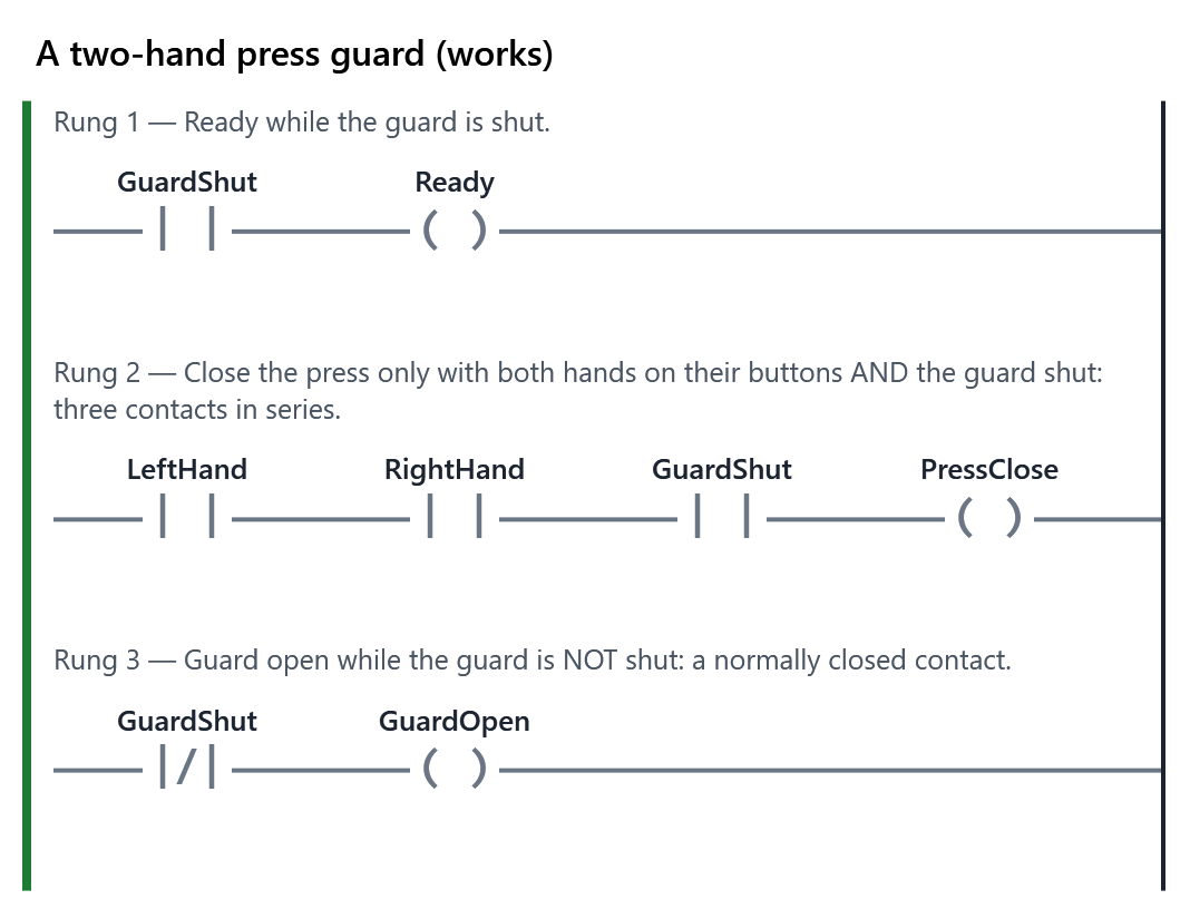
- Rung 1: if the guard is shut, Ready is on.
- Rung 2: if Left hand and Right hand are pressed and the guard is shut, the press closes. Contacts one after the other (in series) make AND: power must pass through every one.
- Rung 3: if the guard is not shut, Guard open is on. A normally closed contact makes NOT.
Contacts side by side (in parallel) make OR: power can pass along either path. You will see that in the seal-in, next.
Try it
Open the Example tab. The rungs run live beside the press: press the hand buttons (hold the mouse down on them) and turn the Guard switch, and watch which rungs pass power. A rung that passes power is drawn green and thick, and its parts say TRUE. Then choose A common mistake in Program: its two hand buttons are side by side (OR). Try one hand alone to see why that is dangerous.
Your comments on this item
3.3 The seal-in circuit
about 30 minutes · builds on 3.2
- Example
- The machine for “Start and stop a pump”, running the working program (also: A common mistake). The working program.
- Exercise
- None: the item is complete when the learner has read it.
- Reference
- The seal-in (holding) circuit, Why Stop is checked with a normally open contact
The Learn tab
The seal-in circuit
A motor, such as a pump's, needs two buttons: Start to run it and Stop to stop it. Push buttons are momentary: they are pressed only while a finger holds them. So how does the motor keep running after you let go of Start?
The answer is the seal-in (also called a holding or latching circuit). The motor contactor has a spare normally open contact, wired in parallel with the Start button. Once the motor is on, that contact is closed, so power has a second path round Start:
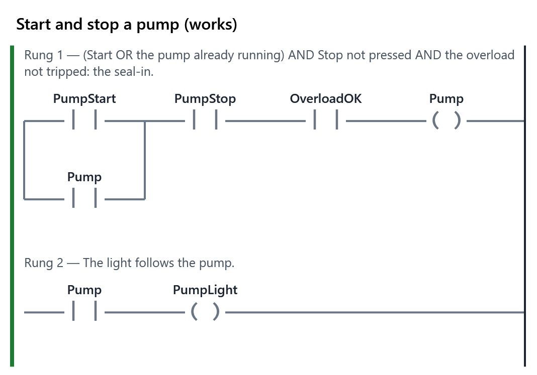
Say rung 1 in words: the pump runs if (Start is pressed OR the pump is already running) AND Stop is not pressed AND the overload relay has not tripped. The overload relay is a protective part every motor starter has: it trips if the motor draws too much current for too long. Leave it out for a moment and the rung is:
Truth table: (PumpStart OR Pump) AND PumpStop
| PumpStart | Pump | PumpStop | (PumpStart OR Pump) AND PumpStop |
|---|---|---|---|
| FALSE | FALSE | FALSE | FALSE |
| FALSE | FALSE | TRUE | FALSE |
| FALSE | TRUE | FALSE | FALSE |
| FALSE | TRUE | TRUE | TRUE ✓ |
| TRUE | FALSE | FALSE | FALSE |
| TRUE | FALSE | TRUE | TRUE ✓ |
| TRUE | TRUE | FALSE | FALSE |
| TRUE | TRUE | TRUE | TRUE ✓ |
Here PumpStop is TRUE while nobody presses it. Find the row where PumpStart is FALSE, Pump is TRUE and PumpStop is TRUE: the result is TRUE, so the pump keeps itself running. Press Stop (PumpStop becomes FALSE) and every row is FALSE: the seal-in breaks, and the pump stays off until Start is pressed again. The overload contact works the same way as Stop: it is wired normally closed, so a trip, or a broken wire, breaks the seal-in.
Why Stop is wired normally closed
The Stop button's contacts are closed until it is pressed, so its input is TRUE while all is well. If the wire to it breaks, the input goes FALSE, which is the same as pressing Stop, and the machine stops. A broken wire fails safe. That is why the program checks Stop with a normally open contact: the contact passes power while the input is TRUE (not pressed). The Reference tab explains this again; it catches out almost everyone once.
Try it
Open the Example tab and run the pump: press Start, let go, then press Stop. Then choose A common mistake in Program: it checks Stop with a normally closed contact, because it is "a stop button". Press Start and see what happens, and why. In module 5 you will write the seal-in yourself, for a motor.
Your comments on this item
3.4 Interlocks
about 25 minutes · builds on 3.3
- Example
- The machine for “Run a conveyor forward and in reverse”, running the working program (also: A common mistake). The working program.
- Exercise
- None: the item is complete when the learner has read it.
- Reference
- Interlocks and limit switches
The Learn tab
Interlocks
Some outputs must never be on together. A motor that runs a door up or down has two contactors: one for each direction. Energize both and the motor is shorted across two phases. Something will burn.
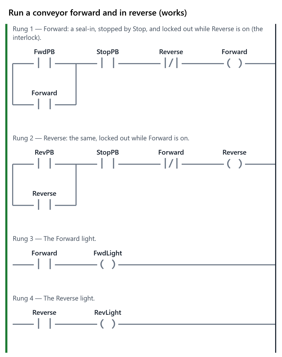
An interlock stops that. Each direction's rung has a normally closed contact of the other direction's coil:
- the Up rung passes power only while Down is not on;
- the Down rung passes power only while Up is not on.
So whichever starts first locks the other out. In a relay panel this is often done twice: in the wiring (electrical interlock) and with a mechanical bar between the two contactors (mechanical interlock), because a welded contact could defeat the first.
Each direction also needs to stop on its own at the end of its travel. A limit switch at the top and one at the bottom do that: each is a normally closed contact in its direction's rung, so reaching the limit breaks the rung.
Try it
The Example tab runs a conveyor motor that can run forward or in reverse: two seal-ins, one per direction, each with an interlock. Press Forward, then press Reverse while it is still running: nothing happens until you press Stop. Choose A common mistake in Program to see the same circuit without the interlocks: press Forward, then Reverse, and read what the motor says.
In module 5 you will write an interlocked program yourself, for a garage door, with limit switches as well.
Your comments on this item
3.5 Module check
about 15 minutes
- Module check
- Complete when every item it covers is: 3.1, 3.2, 3.3, 3.4. Its questions, on the Exercise tab, are below; it is complete when those items are and the questions are passed. Once it is complete, the learner makes the PDF progress report to hand in (Hand in a report).
The Learn tab
Module check: relay control
This check covers the four items of module 3. Each of them is complete once you have read it and pressed I have read this on its Learn tab.
The check itself is six questions, on the Exercise tab: choices, matching symbols, a truth table and a number. You need 80 % to pass, and you can try again as often as you like. A right answer says why; a wrong one tells you to look again, not what the answer is.
When the four items are complete and you have passed the questions, the module is complete and ready to hand in: Hand in a report (the second row of the path) makes the PDF progress report for your instructor.
The questions (on the Exercise tab)
6 questions; the learner needs 80 % to pass and can try again. A wrong answer says “not quite, look again”; the reason is shown once the answer is right. The right answers are marked ✓ here only.
Choose one. A relay's coil is energized. What does a normally closed contact of that relay do?
- It closes
- ✓ It opens
- Nothing: only normally open contacts change
- It closes for one scan, then opens
Why: "Normally" means with the coil off. Energize the coil and every contact changes over: a normally closed contact opens.
Match each one. Match each ladder symbol to what it is.
-| |-→ Normally open contact-|/|-→ Normally closed contact-( )-→ Coil
Why: Contacts read a tag (or a relay's state); the coil at the right-hand end of the rung sets one.
Fill in a truth table. Fill in the seal-in rung's result. Remember that Stop is TRUE while nobody presses it.
Truth table: (Start OR Motor) AND Stop
Start Motor Stop (Start OR Motor) AND Stop FALSE FALSE FALSE FALSE FALSE FALSE TRUE FALSE FALSE TRUE FALSE FALSE FALSE TRUE TRUE TRUE ✓ TRUE FALSE FALSE FALSE TRUE FALSE TRUE TRUE ✓ TRUE TRUE FALSE FALSE TRUE TRUE TRUE TRUE ✓ Why: The motor runs when Start is pressed or it is already running (the seal-in), and Stop is not pressed (TRUE).
Choose one. Why is a Stop button wired normally closed?
- ✓ So a broken wire stops the machine, as if Stop were pressed
- So it uses less power
- Because a PLC can only read closed contacts
- So the program can check it with a normally closed contact
Why: A broken wire makes the input FALSE, the same as pressing Stop: the machine fails safe.
Choose every one that is right. A door motor has an Up contactor and a Down contactor. Which of these are interlocks? Choose every one that is.
- ✓ A normally closed contact of Down in the Up rung
- ✓ A normally closed contact of Up in the Down rung
- Up's own contact in parallel with the Open button
- A limit switch at the top of the travel
Why: An interlock locks one output out while the other is on. Up's own contact is the seal-in, and the limit switch stops the travel.
A number. A contactor coil rated 24 V DC has a resistance of 240 Ω. How much current does it draw, in milliamps?
✓ 100 mA (within 1)
Why: Ohm's law: I = V / R = 24 V / 240 Ω = 0.1 A, which is 100 mA.