← The review guideReference pages
Module 4 · PLC fundamentals
First draft, for your review · about 3.3 hours
Recommended first
Module 3, Relay control (recommended, not enforced)
What the learner will be able to do
- Name the parts of a PLC (power supply, processor, memory, input and output modules, rack, programming software) and say what each does. (plc.m4.o1)
- Explain how discrete input and output modules connect field devices to tags, including sinking and sourcing and the kinds of output. (plc.m4.o2)
- Describe the common sensors (limit switch, float switch, proximity sensor and photo eye) and how they are wired to fail safe. (plc.m4.o3)
- Explain the scan cycle (read the inputs, run the program top to bottom, write the outputs) and what follows from it. (plc.m4.o4)
- Explain tags and addresses, how a tag names an input, an output or a memory value, and its data type. (plc.m4.o5)
Topics
PLC hardware · Input and output modules · Sinking and sourcing · Sensors · The scan cycle · Tags, addresses and data types
About this module
In module 3 you saw machines controlled by panels of relays. A PLC (programmable logic controller) does the same job with a small industrial computer: the wiring stays at the edges, and the logic in the middle becomes a program you can change from a laptop.
This module is about the PLC itself and how it connects to a machine:
- what is inside it, and how its parts fit in a rack;
- how input and output modules connect buttons, sensors, lights and motor contactors, including the sinking and sourcing question that trips up almost everyone in the lab;
- the sensors that tell a program where things are;
- the scan cycle, the loop every PLC program runs in;
- tags and addresses, the names a program uses for every input, output and memory value.
The items are readings with practice questions. Several have an Example tab: one of PLC+'s machines, with things to watch for. Nothing here asks you to write a program yet; that starts in module 5, and everything in this module is what you will need there and in the lab.
The items
Each item has four tabs in PLC+: Learn (the lesson below), Example (a machine running a working program), Exercise (the learner writes the program; PLC+ checks it) and Reference. Every item has a comment box under it.
- 4.1 Inside a PLC
- 4.2 Input and output modules
- 4.3 Sensors
- 4.4 The scan cycle
- 4.5 Tags and addresses
- 4.6 Module check
4.1 Inside a PLC
about 30 minutes
- Example
- None: this item has no machine.
- Exercise
- Practice questions (below). Passing them completes the item.
- Reference
- PLC hardware
The Learn tab
Inside a PLC
A PLC (programmable logic controller) is a computer built for a factory floor. It reads switches and sensors, decides what to do with a program, and turns on lights, valves and motor contactors. It is built to survive heat, dust, vibration and electrical noise, and to run the same program day and night for years.
Why PLCs replaced relay panels
A relay panel's logic is in its wiring. To change what the machine does, an electrician rewires the panel, and every change risks a mistake. A large panel also has hundreds of relays, each of which can wear out.
With a PLC, the buttons and sensors are wired to its inputs, and the lights and contactors to its outputs, once. The logic between them is a program. Changing it means editing the program, not the wires. A PLC also shows you, live, the state of every input and output, which makes faults much faster to find.
The program is still drawn as a ladder, so electricians who knew relay panels could read it. That is why module 3 came first.
The parts
| Part | What it does |
|---|---|
| Power supply | Turns the plant's power (often 120 V AC) into the low DC voltage the PLC's electronics need |
| Processor (CPU) | Runs the program, over and over. Also called the controller |
| Memory | Holds the program and the data (the values of every tag). Kept when the power is off |
| Input modules | Connect the field devices that tell the PLC something: buttons, switches, sensors |
| Output modules | Connect the field devices the PLC controls: lights, solenoid valves, contactor coils |
| Rack (chassis) | The frame the modules plug into. Each position is a numbered slot |
| Communication ports | Connect a programming computer, a touch screen (HMI), other PLCs or a network |
Field devices are the real things out on the machine: the Start button, the float switch, the motor contactor. The PLC never touches a motor directly; it switches the small current of a contactor's coil, and the contactor switches the motor (more in the next item).
Programming software
You write the program on a PC, in the PLC maker's software, and download it to the processor over a cable or a network. The software also lets you go online: watch the program run, with each contact and coil showing whether it passes power, just as PLC+ does. You can upload a program from a PLC to the PC to see what it is running.
Compact and modular PLCs
- A compact (or fixed) PLC has the power supply, processor and a set number of inputs and outputs in one box. It is cheap and small: good for one small machine. Many can take a few plug-in modules for more.
- A modular PLC is built from separate modules in a rack or a row. You choose the processor and add the input and output modules the machine needs. It is good for larger machines and is easy to repair: swap the failed module.
Your lab uses Allen-Bradley PLCs, made by Rockwell Automation. As examples only: the Micro800 family (such as the Micro850) are compact controllers programmed with Connected Components Workbench, and CompactLogix controllers are modular, programmed with Studio 5000 Logix Designer. Older panels may still have SLC 500 or MicroLogix PLCs. Your lab instructor will tell you which model you will use.
Try it
This item has no machine. Open the Exercise tab and answer the practice questions. Each answer says why, and shows the right one when yours is wrong. Pass them (80 %) and the item is complete.
The questions (on the Exercise tab)
4 questions; the learner needs 80 % to pass and can try again. Practice: a wrong answer shows the right one. The right answers are marked ✓ here only.
Match each one. Match each part of a PLC to what it does.
Power supply→ Turns the plant's power into the low DC voltage the electronics needProcessor (CPU)→ Runs the program, over and overInput module→ Connects buttons, switches and sensorsOutput module→ Connects lights, valves and contactor coilsRack (chassis)→ Holds the modules in numbered slots
Why: The processor decides; the input and output modules connect it to the machine; the power supply and the rack hold it all together.
Choose one. What is the main reason PLCs replaced relay panels?
- ✓ The logic is a program: to change what the machine does, you edit the program, not the wiring
- A PLC needs no wiring at all
- A PLC can switch a motor's full current directly
- Relay panels cannot use push buttons
Why: The buttons, sensors and contactors are still wired to the PLC, but only once. The logic between them is a program, which is quick to change and easy to watch running.
Choose every one that is right. Which of these are true of a modular PLC? Choose every one that is.
- ✓ You choose the processor and add the input and output modules the machine needs
- ✓ A failed module can be swapped without replacing the whole PLC
- The power supply, processor and a set number of inputs and outputs are always in one box
- ✓ Each module sits in a numbered slot
Why: Everything in one box describes a compact (fixed) PLC. A modular PLC is built up from separate modules in slots.
Choose one. You write a program on your laptop and copy it into the PLC. What is that called?
- ✓ Downloading
- Uploading
- Scanning
- Forcing
Why: Download is from the PC to the PLC; upload is from the PLC back to the PC.
Your comments on this item
4.2 Input and output modules
about 30 minutes · builds on 4.1
- Example
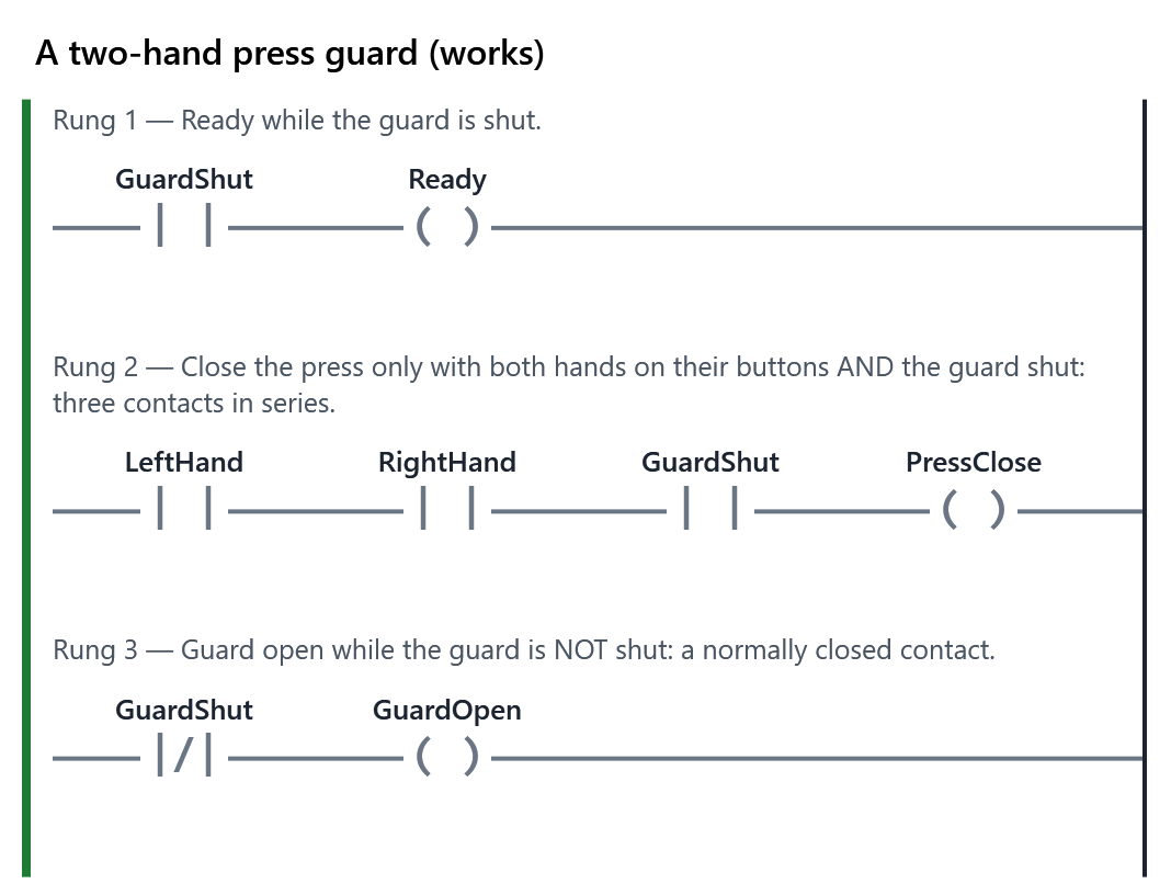
- The machine for “A two-hand press guard”, running the working program (also: A common mistake). The working program.
- Exercise
- Practice questions (below). Passing them completes the item.
- Reference
- Input and output modules, PLC hardware
The Learn tab
Input and output modules
The modules are where the PLC meets the machine. An input module turns a voltage from a field device into a TRUE or FALSE the program can read. An output module turns a TRUE or FALSE from the program into a voltage that works a field device.
This item is about discrete (on/off) inputs and outputs: a button is pressed or not, a light is on or off. Inputs and outputs that carry a range of values, such as a temperature or a valve position, are analog; they come later, in module 9.
From a button to a tag
Follow one signal, from the machine to the program:
- A field device (the Start button) closes and passes voltage down its wire.
- The wire lands on a terminal of the input module.
- That terminal is one input point (also called a channel). Each point has a number: point 0, point 1, …
- The processor reads the point and stores TRUE or FALSE in its tag (Start). The program reads the tag.
An output runs the other way: the program sets a tag, the processor sends it to an output point, and the module switches voltage to the field device on that point's terminal.
Most modules have a status LED for each point. An input LED lit means there is voltage at that terminal. An output LED lit means the program has told the point to turn on. It does not prove the device got power: a blown fuse or a broken wire beyond the terminal still leaves the device off. Checking the LED first, then the wire, is the start of most troubleshooting.
Voltages
Modules are made for one kind of signal. The common ones are 24 V DC (most sensors and new machines) and 120 V AC (common in older US plants). Wire a device of one voltage to a module of another and it will not work, or the module will be damaged. The module's label and its wiring diagram say what it takes.
Sinking and sourcing
With 24 V DC, current must flow in a loop: from +24 V, through the device, through the input point, and back to 0 V (the common). The two words say which side of the load a device is on. Here "current" means conventional current, flowing from + to −.
- A sourcing device supplies current: it switches the +24 V side and sends current out. A PNP sensor is sourcing.
- A sinking device takes in current and gives it a path to 0 V. An NPN sensor is sinking.
The rule: one side sources, the other sinks. A sourcing (PNP) sensor needs a sinking input module, whose points lead through the module to 0 V. A sinking (NPN) sensor needs a sourcing input module. Pair two sourcing devices, or two sinking ones, and no current can flow: the input never turns on.
Many DC input modules can be wired either way, by what you connect to the module's common terminal. Always check the module's wiring diagram. The same words are used for DC outputs: a sourcing output sends +24 V out to the load.
Kinds of output
| Output | Switches | Good for | Watch out |
|---|---|---|---|
| Relay | AC or DC | Mixed voltages, a few amps | Slow, and the contacts wear out |
| Transistor | DC only | Fast switching, long life | Small currents; sinking or sourcing |
| Triac | AC only | AC loads, long life | Small leakage current when off |
An output point can carry only a small current, often an amp or less. A motor needs far more. So the output drives the coil of a contactor (or a motor starter), and the contactor's heavy contacts switch the motor, exactly as in module 3. This also keeps the motor's power wiring away from the PLC.
Try it
Open the Example tab: a press guard station. Open The wiring: which tag is which under the machine: LeftHand, RightHand and GuardShut are inputs, and Ready, PressClose and GuardOpen are outputs. Turn the Guard switch and watch its tag turn TRUE on the rungs, then the Ready light's tag. Then answer the questions on the Exercise tab.
The questions (on the Exercise tab)
5 questions; the learner needs 80 % to pass and can try again. Practice: a wrong answer shows the right one. The right answers are marked ✓ here only.
Choose one. A proximity sensor has a PNP (sourcing) output: it switches +24 V out to the input. Which kind of DC input does it need?
- ✓ A sinking input, which gives the current a path to 0 V
- A sourcing input, which also supplies +24 V
- A relay output
- Any input: sinking and sourcing do not matter for DC
Why: One side sources, the other sinks. Current flows out of the sourcing sensor, through the input point, and back to 0 V through a sinking input.
Choose one. Why does a PLC output drive a contactor coil rather than the motor itself?
- ✓ An output point can carry only a small current; the contactor's heavy contacts switch the motor
- PLC outputs can only switch DC
- A motor needs a normally closed contact
- The contactor makes the program run faster
Why: An output point is rated for an amp or so at most. The contactor's coil needs little current, and its main contacts carry the motor's large current, away from the PLC.
Match each one. Match each kind of output to what it switches.
Relay output→ AC or DC; slow, and its contacts wearTransistor output→ DC only; fast, with a long lifeTriac output→ AC only; a small leakage current when off
Why: A relay is a switch, so it takes either voltage. A transistor switches DC and a triac switches AC, both with no moving parts.
Choose one. The LED for output point 3 is lit, but the pilot light wired to point 3 is off. What does that tell you?
- ✓ The program has turned the point on, so look beyond the module: the fuse, the wire, the lamp
- The program has not turned the point on
- The input module is faulty
- The PLC is not in Run mode
Why: An output LED shows what the PLC has told the point to do. It does not prove the device got power.
A number. An input module has 16 points, numbered from 0. What is the number of its last point?
✓ 15 (within 0)
Why: Points are numbered from 0, so 16 points are 0 to 15.
Your comments on this item
4.3 Sensors
about 30 minutes · builds on 4.2
- Example
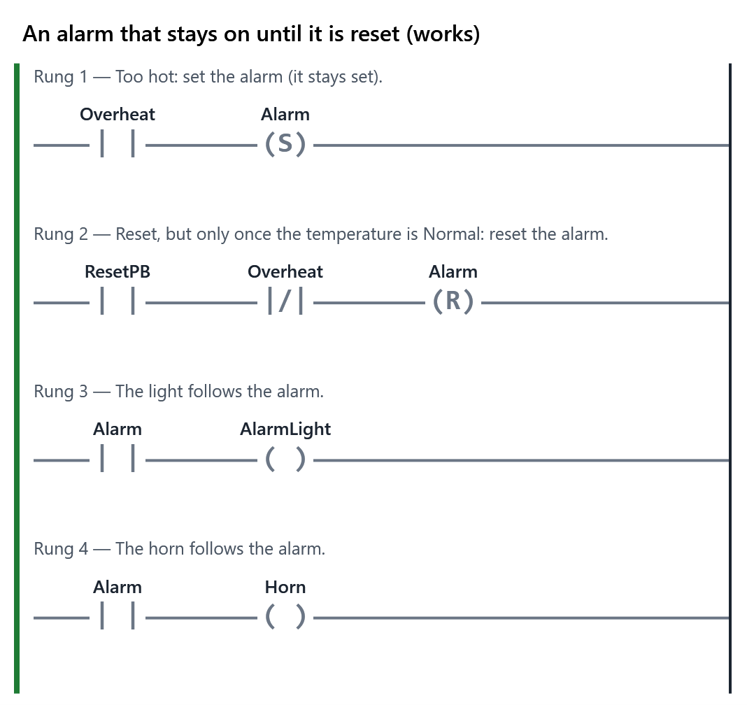
- The machine for “An alarm that stays on until it is reset”, running the working program (also: A common mistake). The working program.
- Exercise
- Practice questions (below). Passing them completes the item.
- Reference
- Sensors, Why Stop is checked with a normally open contact
The Learn tab
Sensors
A program can only act on what it is told. Sensors tell it where things are: is the door at the top, is the tank full, is a part in front of the diverter? Each sensor here is discrete: its input is TRUE or FALSE.
The common sensors
- A limit switch has a lever or plunger. A moving part pushes it, and its contacts change over. It tells the program that something has reached a place: the garage door at the top or the bottom of its travel.
- A float switch floats on a liquid. When the level rises to it, it lifts and its contacts change over. The tank in PLC+ has two: a low float at 20 % and a high float at 80 %.
- A proximity sensor (a prox) senses an object near its face without touching it. An inductive prox senses only metal, which is how the conveyor sorter tells metal parts from plastic. A capacitive prox senses almost anything, including plastic, wood and liquid, even through the wall of a plastic tank.
- A photo eye (photoelectric sensor) uses a beam of light. Something in the way breaks the beam.
Three ways to set up a photo eye
| Kind | How it works |
|---|---|
| Through-beam | A sender on one side, a receiver on the other. Longest range, most reliable |
| Retro-reflective | Sender and receiver in one body, aimed at a reflector across the gap |
| Diffuse | Sender and receiver in one body; the light bounces back off the object itself. Shortest range |
Most photo eyes can be set to light operate (the output is on while the receiver sees light: the beam is clear) or dark operate (on while the beam is blocked). In PLC+, the garage door's safety eye works like light operate: EyeClear is TRUE while the doorway is clear. The conveyor's photo eye works like dark operate: Eye is TRUE while a part is in front of it.
Wiring to fail safe
A sensor's contacts can be wired normally open (the input turns TRUE when it senses its target) or normally closed (the input is TRUE until it senses its target). Choose with this question: if this wire breaks, what will the program think?
A broken wire always reads FALSE. So a signal that must stop the machine, such as a Stop button or a safety eye, is wired so that FALSE means "stop". Then a broken wire stops the machine, just as pressing Stop would. That is failing safe, and it is why the Stop button and the safety eye in PLC+ are TRUE while all is well. The wiring list under each machine says which way each sensor is wired; read it before you write a contact.
Two-wire and three-wire sensors
A limit switch or float switch is just a contact: two wires, in series with the input. Electronic sensors such as a prox or a photo eye need power to run, so most are three-wire: +24 V, 0 V, and an output wire to the input point. The output is either PNP (sourcing) or NPN (sinking), and must match the input module (item 4.2). Some electronic sensors are two-wire, wired in series like a switch; they let a small current through even when off, which can confuse some input modules.
Try it
Open the Example tab: an overheat alarm. Its temperature switch is a sensor: a thermostat whose contact closes when the oven is too hot (in PLC+ you turn it by hand, to play the oven). Turn it to Too hot and watch Overheat turn TRUE on the rungs. Then ask: if the wire to this switch broke, what would Overheat read, and would anyone know? (It would read FALSE, the same as Normal, so nobody would know: this switch fails unsafe. A real overheat switch is wired normally closed, like a Stop button.) The -(S)- and -(R)- coils in its program are explained in 5.4; for now, watch the Overheat contact. You will meet the conveyor's proximity sensor and photo eye in module 5. Then answer the questions on the Exercise tab.
The questions (on the Exercise tab)
5 questions; the learner needs 80 % to pass and can try again. Practice: a wrong answer shows the right one. The right answers are marked ✓ here only.
Match each one. Match each sensor to what it senses.
Limit switch→ A moving part pushing its leverFloat switch→ A liquid rising to its heightInductive proximity sensor→ Metal near its face, without touchingPhoto eye→ Something breaking a beam of light
Why: Limit switches touch; proximity sensors and photo eyes do not. An inductive prox senses metal only.
Choose one. You need to sense plastic bottles on a conveyor, without touching them. Which sensor will not work?
- ✓ An inductive proximity sensor
- A capacitive proximity sensor
- A through-beam photo eye
- A diffuse photo eye
Why: An inductive prox senses only metal. That is how the conveyor sorter in PLC+ tells metal parts from plastic ones.
Choose one. The conveyor's photo eye turns its output on while a part is blocking the beam. How is it set up?
- ✓ Dark operate
- Light operate
- Normally closed
- Through-beam
Why: Dark operate: on while the receiver is dark (the beam is blocked). Light operate is on while the beam is clear, like the garage door's safety eye.
Choose one. The garage door's safety eye is wired so that EyeClear is TRUE while the doorway is clear. What happens if its wire breaks?
- ✓ EyeClear reads FALSE, as if something were in the doorway, so the door will not come down: it fails safe
- EyeClear reads TRUE, so the door comes down on whatever is there
- The PLC stops with a fault
- Nothing changes
Why: A broken wire always reads FALSE. Wiring a safety signal so that FALSE means stop makes a broken wire stop the machine.
Choose every one that is right. Which of these are usually three-wire sensors (+24 V, 0 V and an output)? Choose every one.
- ✓ Inductive proximity sensor
- ✓ Photo eye
- Mechanical limit switch
- Float switch
Why: Electronic sensors need power to run, so most have three wires. A limit switch or a float switch is just a contact: two wires.
Your comments on this item
4.4 The scan cycle
about 30 minutes · builds on 4.3
- Example
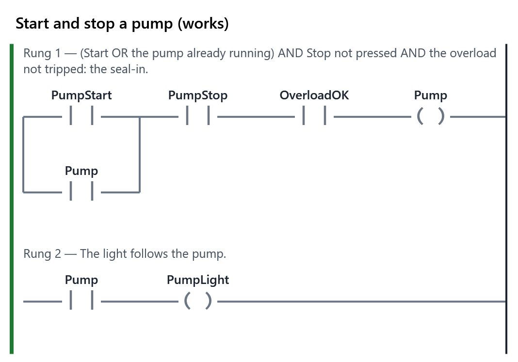
- The machine for “Start and stop a pump”, running the working program (also: A common mistake). The working program.
- Exercise
- Practice questions (below). Passing them completes the item.
- Reference
- The scan cycle
The Learn tab
The scan cycle
A PLC does not run its program once. It runs it over and over, as fast as it can, for as long as it is in Run mode. Each pass is called a scan, and every pass has the same steps:
- Read the inputs. The processor reads every input point and copies its state into the input's tag.
- Run the program. It works through every rung, top to bottom, left to right, using those copies.
- Write the outputs. It copies every output tag to its output point.
- Housekeeping. It talks to the programming software and the network, and checks itself. Then it starts again.
The time one pass takes is the scan time. On a real PLC it is often a few milliseconds, longer for a large program. The processor has a watchdog timer: if a scan ever takes too long, the PLC stops with a fault rather than run a machine it is no longer keeping up with.
In PLC+, one scan is 10 ms of simulated time, so the program runs 100 times every simulated second.
What follows from the cycle
The program sees a snapshot. The inputs are copied once, at the start. If a button changes while the rungs are being worked through, the program does not see it until the next scan. Every rung in one scan sees the same input values.
Rungs run in order, and the last word counts. A coil sets its tag as soon as its rung runs, and a rung further down reads the new value in the same scan. But if two rungs both have a coil of the same tag, the later rung overwrites the earlier one, and only the last value is written to the output. This is the double coil mistake:
- rung 1: Start → Motor
- rung 5: Jog → Motor
When Start is pressed and Jog is not, rung 1 turns Motor on, then rung 5 turns it off again, in the same scan. The motor never runs from Start. The fix is one coil per output: put Start and Jog in parallel on one rung. (Set and reset coils, in module 5, are the exception: they are meant to be used in pairs.)
A very short pulse can be missed. The inputs are read once per scan. If a sensor turns on and off again between two reads, the program never sees it. With a 10 ms scan, a pulse of 3 ms can fall between two reads. Slow scans and fast parts need care: a faster task, or a special input module that catches pulses.
Outputs change at the end. Nothing reaches the machine until the scan's outputs are written, so a coil that is turned on and off within one scan never moves anything.
Not every PLC works exactly this way
The four steps above are the classic cycle, and SLC 500 and MicroLogix PLCs work this way. Allen-Bradley's Logix controllers (CompactLogix, ControlLogix) update their inputs and outputs on a timer of their own (the RPI, requested packet interval), not once per scan, so an input can change in the middle of a scan. Programmers who need a steady value copy their inputs at the top of the program. PLC+ uses the classic cycle.
Try it
Open the Example tab: a pump station. Press Pause, tick keep pressed under Start, and press Step one scan. In that one scan, rung 1 turns Pump on, and rung 2, further down, already sees it and lights PumpLight. Untick keep pressed (that lets go of Start) and step again: the Pump contact on the branch keeps rung 1 passing power. Press Run (the Pause button, while paused) to let it run on. The pump also has an overload relay in series; you will meet those in module 5. Then answer the questions on the Exercise tab.
The questions (on the Exercise tab)
5 questions; the learner needs 80 % to pass and can try again. Practice: a wrong answer shows the right one. The right answers are marked ✓ here only.
Choose one. In what order does a PLC do the steps of one scan?
- ✓ Read the inputs, run the program, write the outputs, housekeeping
- Run the program, read the inputs, write the outputs, housekeeping
- Write the outputs, read the inputs, run the program, housekeeping
- Read the inputs and write the outputs at once, then run the program
Why: The program works on a snapshot of the inputs, and its results go out together at the end.
A number. In PLC+ one scan is 10 ms. How many scans run in one second?
✓ 100 scans (within 0)
Why: 1 s = 1000 ms, and 1000 ms / 10 ms = 100 scans.
Choose one. Rung 1 is Start → Motor. Rung 5 is Jog → Motor. Start is pressed and Jog is not. What does the motor do?
- ✓ It stays off: rung 5 runs later and turns Motor off again in the same scan
- It runs: rung 1 turned it on
- It flickers on and off every scan
- The PLC stops with a fault
Why: Two coils of one tag is the double coil mistake: the later rung overwrites the earlier one, and only the last value is written out.
Choose one. The scan is 10 ms. A sensor turns on for 3 ms between two reads of the inputs. What does the program see?
- ✓ Nothing: the pulse came and went between two reads
- The pulse, for one scan
- The pulse, for 3 ms
- The pulse, for three scans
Why: Inputs are read once per scan. A pulse shorter than a scan can fall between two reads and be missed.
Choose one. A button is pressed while the processor is working on rung 10 of 20. When does rung 3 see it?
- ✓ In the next scan, after the inputs are read again
- At once, in this scan
- Only after a power cycle
- When the outputs are written
Why: The inputs are copied once, at the start of each scan. Every rung in one scan sees the same snapshot.
Your comments on this item
4.5 Tags and addresses
about 30 minutes · builds on 4.4
- Example
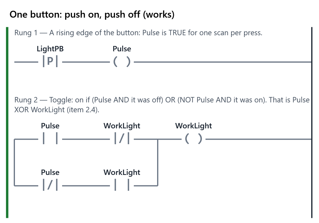
- The machine for “One button: push on, push off”, running the working program (also: A common mistake). The working program.
- Exercise
- Practice questions (below). Passing them completes the item.
- Reference
- Tags
The Learn tab
Tags and addresses
Every value a program uses has a place in the PLC's memory. An address says where that place is: which module, which point. A tag gives it a name people can read. Local:1:I.Data.0 is an address; Start is a tag. A program written with good tag names reads almost like the brief.
Three kinds of tag
| Kind | What it holds | Who sets it | Example in PLC+ |
|---|---|---|---|
| Input | The state of an input point | The PLC, at the start of each scan | Start, HighFloat, Prox |
| Output | What an output point should do | The program; written out at the end of the scan | Motor, FillValve, Divert |
| Memory (internal) | A value only the program uses | The program | Filling, MetalSeen |
A memory tag is not wired to anything. It is the PLC's version of a spare relay: a place to remember something, such as "the tank is filling".
Data types
Each tag has a data type: what kind of value it holds and how much memory it takes.
| Type | Holds | Example |
|---|---|---|
| BOOL | TRUE or FALSE (1 or 0): one bit | Start, Motor |
| INT | A whole number, −32,768 to 32,767 (16 bits) | A count of parts |
| DINT | A whole number, about ±2.1 billion (32 bits) | A large count, a time in ms |
| REAL | A number with a decimal point | 72.5 (a temperature) |
| TIME | A length of time (IEC) | T#5s for a timer's preset |
Every discrete input and output is a BOOL. Allen-Bradley's Logix controllers use DINT for most whole numbers, and their timers keep the preset as a DINT number of milliseconds instead of a TIME.
Addresses on different PLCs
The same input point is written differently on different PLCs. These are examples of the forms you will meet:
| PLC | An input | An output | A memory bit |
|---|---|---|---|
| IEC 61131-3 | %IX0.0 |
%QX0.1 |
%MX0.0 |
| Allen-Bradley Logix (CompactLogix) | Local:1:I.Data.0 |
Local:2:O.Data.3 |
a tag you create |
| Allen-Bradley SLC 500, MicroLogix | I:1/0 |
O:2/3 |
B3:0/1 |
Read them like this:
%IX0.0is an Input, one bit (X), byte 0, bit 0.%Qis an output,%Mmemory.Local:1:I.Data.0is the module in slot 1 of this controller's own rack, its Input data, bit 0. The exact form depends on the module, and the software shows it for you.I:1/0is the Input file, slot 1, bit 0.O:2/3is the Output file, slot 2, bit 3.B3:0/1is the Bit file number 3, word 0, bit 1: a memory bit.
Micro800 controllers name their built-in points another way again, such as _IO_EM_DI_00 (embedded digital input 0). On a Logix controller you give a point a readable name with an alias tag: Start, an alias for Local:1:I.Data.0.
Good tag names
- Say what it means, not where it is wired: HighFloat, not Input3.
- For a signal wired normally closed, say which way is TRUE: StopPB with a comment "TRUE until pressed", or EyeClear.
- Be consistent: PB for push buttons, a noun for an output (FillValve).
- No spaces. Many PLCs do not allow them.
Try it
Open the Example tab: one button that turns a work light on and off. Open The wiring: which tag is which. In PLC+ that list is the tag list for the machine's inputs and outputs: LightPB is an input and WorkLight an output. Pulse is a memory tag, so it is not in the list. Press the button and watch all three on the rungs. Pulse is TRUE for only one scan; to catch it, press Pause, tick keep pressed under the Light button, and press Step one scan: Pulse is TRUE. Press Step one scan again and it is FALSE, though the button is still held. (The -|P|- contact that does this is explained in 5.5.) Then answer the questions on the Exercise tab.
The questions (on the Exercise tab)
5 questions; the learner needs 80 % to pass and can try again. Practice: a wrong answer shows the right one. The right answers are marked ✓ here only.
Match each one. The tank in PLC+ has these tags. Match each to its kind.
HighFloat→ An input: set by the machineFillValve→ An output: set by the program, sent to the machineFilling→ A memory tag: used only by the program
Why: HighFloat is wired to an input point, FillValve to an output point, and Filling is not wired to anything: it remembers that the tank is filling.
Match each one. Match each data type to what it holds.
BOOL→ TRUE or FALSEINT→ A whole number from -32,768 to 32,767REAL→ A number with a decimal pointTIME→ A length of time, such as T#5s
Why: Every discrete input and output is a BOOL. DINT is a larger whole number (32 bits).
Choose one. On an SLC 500 or MicroLogix PLC, what is
I:1/0?- ✓ Input, slot 1, bit 0
- Output, slot 1, bit 0
- Input, slot 0, bit 1
- Integer number 1, value 0
Why: I is the input file, 1 is the slot, and /0 is the bit. O:2/3 would be output, slot 2, bit 3.
Type the answer. Write the IEC address of output byte 0, bit 1.
✓ %QX0.1 or %Q0.1 (case, spaces and underscores do not matter)
Why: %Q is an output, X a single bit, then byte 0, bit 1. An input would be %IX, a memory bit %MX.
Choose one. Which is the best tag name for the float switch at the top of a tank?
- ✓ HighFloat
- Input3
- I:1/3
- high float switch
Why: Name a tag for what it means, not where it is wired. Many PLCs do not allow spaces in names.
Your comments on this item
4.6 Module check
about 15 minutes
- Module check
- Complete when every item it covers is: 4.1, 4.2, 4.3, 4.4, 4.5. Its questions, on the Exercise tab, are below; it is complete when those items are and the questions are passed. Once it is complete, the learner makes the PDF progress report to hand in (Hand in a report).
The Learn tab
Module check: PLC fundamentals
This check covers the five items of module 4. Each of them is complete when you pass its practice questions on its Exercise tab.
The check itself is ten questions, on the Exercise tab: choices, matching, numbers, a typed address, and two find the fault questions. In those, a machine runs its working program, but one of its inputs has a wiring fault. Work the machine, watch the rungs and the wiring list, and say what is wrong. You need 80 % to pass, and you can try again as often as you like. A right answer says why; a wrong one tells you to look again, not what the answer is.
When the five items are complete and you have passed the questions, the module is complete and ready to hand in: Hand in a report (the second row of the path) makes the PDF progress report for your instructor.
The questions (on the Exercise tab)
10 questions; the learner needs 80 % to pass and can try again. A wrong answer says “not quite, look again”; the reason is shown once the answer is right. The right answers are marked ✓ here only.
Choose one. Which part of a PLC runs the program?
- ✓ The processor (CPU)
- The power supply
- The input module
- The rack
Why: The processor reads the inputs, runs the program and writes the outputs. The modules connect it to the machine; the rack holds them.
Choose one. A small machine needs 8 inputs and 6 outputs, and will never grow. Which kind of PLC fits best?
- ✓ A compact PLC: power supply, processor, inputs and outputs in one box
- A modular PLC with a large rack
- Two PLCs, one for inputs and one for outputs
- No PLC: only relays can do this
Why: A compact (fixed) PLC is small and cheap, and has enough points for a small machine. A modular PLC suits larger machines that need more or different modules.
Choose one. A photo eye has an NPN (sinking) output: it connects the input to 0 V when it sees a part. Which kind of DC input does it need?
- ✓ A sourcing input, which supplies the current
- A sinking input, which also connects to 0 V
- A triac output
- A 120 V AC input
Why: One side sources, the other sinks. A sinking sensor needs a sourcing input to supply the current it takes to 0 V.
Choose every one that is right. Which of these field devices are wired to an output module? Choose every one.
- ✓ A pilot light
- ✓ A solenoid valve
- ✓ A motor contactor's coil
- A limit switch
- A float switch
Why: Outputs drive things the PLC controls. Limit switches and float switches tell the PLC something, so they are inputs.
Find the fault: a machine with a faulty wire, running the working program. This overheat alarm runs the working program, but one input has a wiring fault. Turn the Thermostat to Too hot, press Alarm reset on the machine, and watch the alarm and the rungs. Which fault does it have?
Machine: An alarm that stays on until it is reset; the fault:
Overheat:open- ✓ The thermostat's wire is broken: Overheat always reads FALSE
- The thermostat is shorted: Overheat always reads TRUE
- The Alarm reset button is shorted: ResetPB always reads TRUE
- The Alarm reset button's wire is broken: ResetPB always reads FALSE
Why: The alarm never comes on, however hot it gets: on the rungs, Overheat stays FALSE in Too hot. A broken wire reads the same as "all is well", so this switch fails unsafe. That is why sensors that guard against danger are wired so that a broken wire looks like the danger (normally closed), as the Stop button is.
Find the fault: a machine with a faulty wire, running the working program. This press guard runs the working program, but one input has a wiring fault. Leave the Guard switch at Open, then press both hand buttons, and watch the lights and the rungs. Which fault does it have?
Machine: A two-hand press guard; the fault:
GuardShut:shorted- ✓ The guard switch is shorted: GuardShut always reads TRUE, even with the guard open
- The guard switch's wire is broken: GuardShut always reads FALSE
- The Left hand button is shorted: LeftHand always reads TRUE
- The Right hand button's wire is broken: RightHand always reads FALSE
Why: With the guard open, Ready is lit, Guard open is dark, and both hands close the press: on the rungs GuardShut reads TRUE whatever the switch does. A broken guard-switch wire would keep the press from ever closing, and a faulty hand button would change what the hands do, not the guard lights.
A number. A PLC's scan time is 5 ms. How many times does it read its inputs in one second?
✓ 200 times (within 0)
Why: The inputs are read once per scan: 1000 ms / 5 ms = 200 scans a second.
Choose one. A program has a coil of Pump on rung 2 and another coil of Pump on rung 9. Rung 2 passes power; rung 9 does not. What is written to the Pump output at the end of the scan?
- ✓ FALSE: rung 9 runs later and overwrites rung 2
- TRUE: rung 2 turned it on first
- TRUE for half the scan, then FALSE
- Nothing: the PLC refuses to run the program
Why: Rungs run top to bottom, and the last coil of a tag wins. This double coil mistake is fixed by putting both conditions in parallel on one rung.
Type the answer. Write the IEC address of input byte 0, bit 2.
✓ %IX0.2 or %I0.2 (case, spaces and underscores do not matter)
Why: %I is an input, X a single bit, then byte 0, bit 2. An output would be %QX0.2.
Match each one. Match each Allen-Bradley address to what it is.
I:1/0→ SLC or MicroLogix: input, slot 1, bit 0O:2/3→ SLC or MicroLogix: output, slot 2, bit 3B3:0/1→ SLC or MicroLogix: a memory bit, file B3, word 0, bit 1Local:1:I.Data.0→ Logix: the input module in slot 1, bit 0
Why: The older SLC and MicroLogix PLCs use file letters (I, O, B); Logix controllers name the module's slot and its data. Either way, a good program gives the point a readable tag name.