← The review guideReference pages
Module 6 · Timers and counters
First draft, for your review · about 5 hours
Recommended first
Module 5, Basic ladder programming (recommended, not enforced)
What the learner will be able to do
- Use on-delay, off-delay and pulse timers (TON, TOF, TP) to time events. (plc.m6.o1)
- Use a retentive timer (TONR; RTO on Allen-Bradley) to add up time over several runs, and explain when a timer must keep its time through a stop. (plc.m6.o2)
- Count events with up, down and up/down counters (CTU, CTD, CTUD). (plc.m6.o3)
- Cascade timers and counters to time or count beyond one instruction. (plc.m6.o4)
Topics
On-delay timers (TON) · Off-delay and pulse timers (TOF, TP) · Retentive timing (TONR, RTO) · Counters (CTU, CTD, CTUD) · Cascading timers and counters
About this module
Module 5's programs react at once: press a button, and the coil turns on in the same scan. Real machines also need to wait and to count. A conveyor sounds a warning before it moves; a fan runs on after a heater turns off; a pump needs a service after so many hours; a packer stops after so many bottles. This module gives you the instructions that do it: timers, which measure how long something has been on or off, and counters, which count how many times something has happened.
Each is a box on a rung, with a few values to fill in, and members you can use on contacts, such as T1.Q (the timer is done) and C1.CV (the count so far). You will meet the Allen-Bradley names beside the IEC ones, so the lab's PLC looks familiar.
Each item has two machines, as in module 5: the Example tab runs a working program on a machine like the exercise's, with a common mistake beside it, and the Exercise tab is yours to program and check. Many tests here check when something happens, to a few hundredths of a second, so watch the timers' times count on the rungs as the machines run.
The items
Each item has four tabs in PLC+: Learn (the lesson below), Example (a machine running a working program), Exercise (the learner writes the program; PLC+ checks it) and Reference. Every item has a comment box under it.
- 6.1 On-delay timers: a traffic light
- 6.2 Off-delay and pulse timers: an exhaust fan
- 6.3 Retentive timing: a pump's service light
- 6.4 Counters: parts in a batch
- 6.5 Cascading timers and counters: a case packer
- 6.6 Module check
6.1 On-delay timers: a traffic light
about 50 minutes · builds on 5.2
- Example
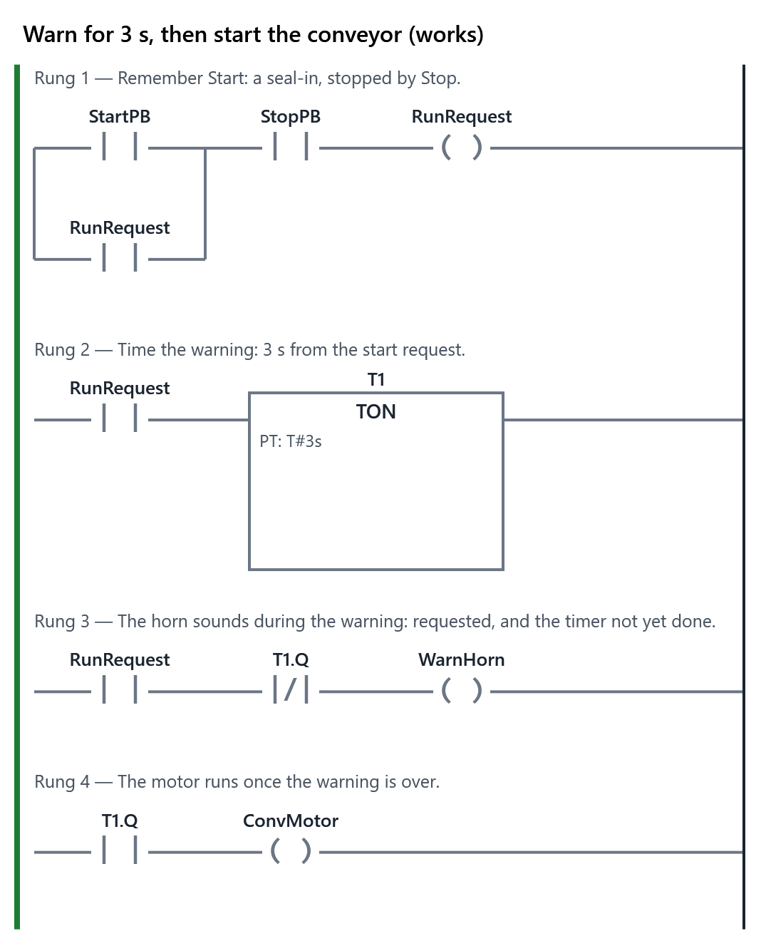
- The machine for “Warn for 3 s, then start the conveyor”, running the working program (also: A common mistake). The working program.
- Exercise
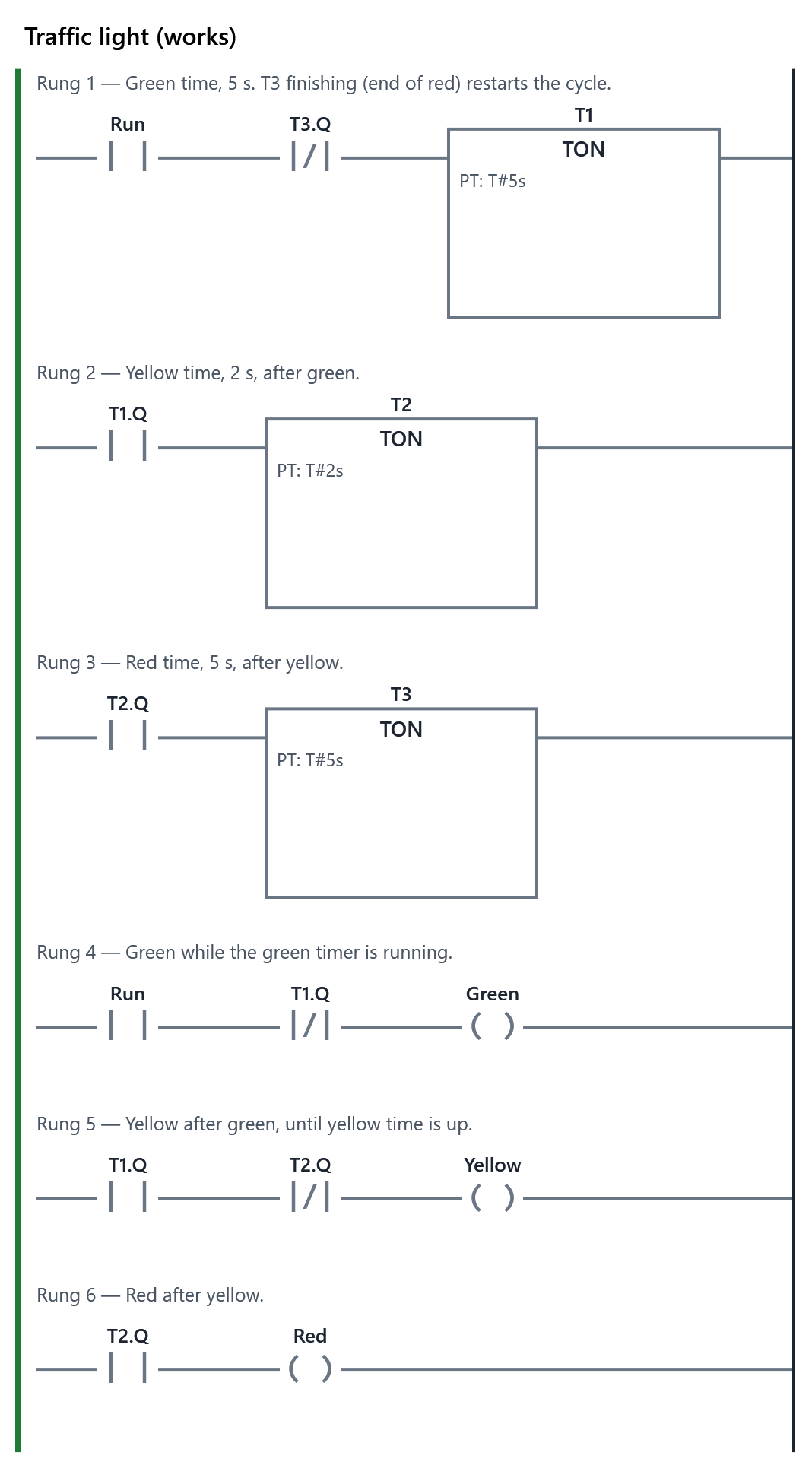
- The learner writes the program for: With the Run switch on: green for 5 s, then yellow for 2 s, then red for 5 s, over and over. Only one light at a time. With Run off, all the lights are off. PLC+ checks it with 3 tests (1 hidden). Passing every test completes the item.
- Reference
- Timers
The Learn tab
On-delay timers: a traffic light
A timer is a box on a rung that measures time. The PLC keeps the time itself, from its own clock, so a program can say "wait 3 seconds" without counting scans.
The most used timer is the on-delay timer, TON. It waits: when power reaches it, it starts timing, and only after a set time does it say "done". A TON has four values:
| Value | What it is |
|---|---|
| IN | the power into the box from the left: TRUE starts the timing |
| PT | the preset time: how long to wait, written like T#3s (3 seconds) or T#500ms |
| ET | the elapsed time: how long IN has been on so far; it stops at PT |
| Q | the output: turns TRUE when ET reaches PT, while IN is still on |
The most important rule: when IN goes FALSE, a TON resets at once. Q goes FALSE and ET goes back to 0, however far it had got. A TON only says "done" if IN stays on for the whole time.
A timing diagram, in a table
A TON with PT T#3s. IN turns on at 1 s, off at 6 s, on again at 7 s and off at 8 s:
| Time | IN | ET | Q |
|---|---|---|---|
| 0 s | FALSE | 0 s | FALSE |
| 1 s | TRUE | 0 s | FALSE |
| 2.5 s | TRUE | 1.5 s | FALSE |
| 4 s | TRUE | 3 s | TRUE |
| 5 s | TRUE | 3 s (stops at PT) | TRUE |
| 6 s | FALSE | 0 s | FALSE |
| 7.5 s | TRUE | 0.5 s | FALSE |
| 8 s | FALSE | 0 s | FALSE (it never got to 3 s) |
Q turns on exactly PT after IN turns on: 1 s + 3 s = 4 s. PLC+ scans every 10 ms, so it is on time to the scan.
Using the timer's output
A timer called T1 has members you use like tags: T1.Q on a contact (normally open passes power once the time is up; normally closed passes power until it is up) and T1.ET in a box that compares numbers (module 7).
Worked example: a start-up warning. A conveyor must sound a horn for 3 s before it moves, so nobody is caught by it:
- A seal-in remembers Start: RunRequest = (StartPB OR RunRequest) AND StopPB.
- RunRequest drives a TON, T1, with PT T#3s.
- The horn sounds while RunRequest AND NOT T1.Q: during the 3 s.
- The motor runs on T1.Q: after the 3 s.
Stop drops RunRequest, which resets the timer, so the next start gets the full 3 s again.
Allen-Bradley
The lab's PLC has the same TON, drawn as a box with a timer tag (such as Warn_Timer). Its members have other names:
| IEC (PLC+) | Allen-Bradley | Meaning |
|---|---|---|
| PT | .PRE | the preset, in milliseconds: 3 s is 3000 |
| ET | .ACC | the accumulated time, in milliseconds |
| Q | .DN | done |
| IN | .EN | enabled: the rung is TRUE |
| .TT | timer timing: enabled and not yet done |
So NOT T1.Q in the horn rung would be an XIO of Warn_Timer.DN, and T1.Q in the motor rung an XIC of Warn_Timer.DN.
How to do it
- Open the Example tab: the conveyor with the warning horn. Press Start, let go, and watch T1's ET count up beside its box; the motor starts when it reaches 3 s. Press Stop during the warning, then Start again. Then choose A common mistake in Program, above the machine: its timer is started by the Start button itself. Let go of Start and watch ET go back to 0.
- Open the Exercise tab: the traffic light. With Run on: green 5 s, yellow 2 s, red 5 s, over and over. Use three TONs in a chain: each starts when the one before it is done, and the last one finishing restarts the first: how? Think about what resets a TON.
- To add a timer, select the contact on a rung and choose Box ▾ ▸ Timers ▸ TON. The box gets its own tag (T1, then T2, …) and PT T#1s: type the time in its PT box above the rungs and press Enter. If the rung has a coil you do not need, select it and press Delete.
- Each light's rung uses the timers' Q contacts. Press Check my program. The tests check when yellow and red come on, to within 0.05 s.
Your comments on this item
6.2 Off-delay and pulse timers: an exhaust fan
about 40 minutes · builds on 6.1
- Example
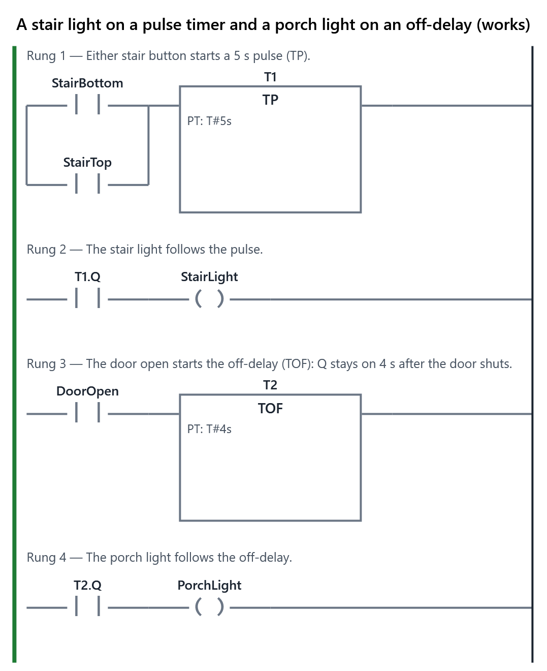
- The machine for “A stair light on a pulse timer and a porch light on an off-delay”, running the working program (also: A common mistake). The working program.
- Exercise
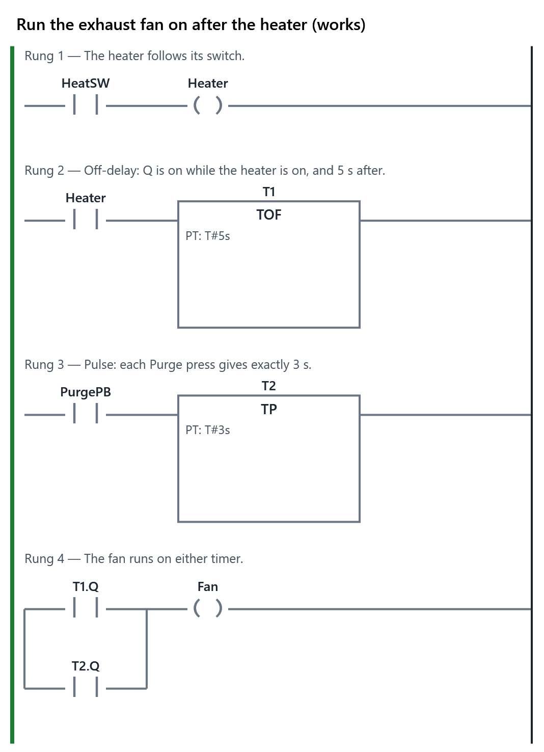
- The learner writes the program for: The heater is on while the Heater switch is On. The exhaust fan runs while the heater is on, and keeps running for 5 s after the heater turns off, to clear the fumes. Each press of Purge also runs the fan for exactly 3 s, however long the button is held. PLC+ checks it with 4 tests (1 hidden). Passing every test completes the item.
- Reference
- Timers, Off-delay and pulse timers
The Learn tab
Off-delay and pulse timers: an exhaust fan
A TON delays turning on. Two more timers handle the other jobs that come up again and again: keeping something on for a while after its signal goes off, and giving a fixed-length pulse whatever the signal does.
The off-delay timer, TOF
An off-delay timer keeps its output on for a while after its input goes off:
- while IN is TRUE, Q is TRUE (at once, with no delay) and ET is 0;
- when IN goes FALSE, the timing starts: Q stays TRUE until ET reaches PT, then goes FALSE;
- if IN comes back on before then, Q simply stays on, and the timing starts again from 0 the next time IN goes off.
Uses: a fan that clears fumes after a heater turns off, a cooling pump that runs on after a motor stops, a porch light that stays on after a door shuts.
A TOF with PT T#4s; IN on at 1 s, off at 3 s:
| Time | IN | ET | Q |
|---|---|---|---|
| 0 s | FALSE | 0 s | FALSE |
| 1 s | TRUE | 0 s | TRUE |
| 3 s | FALSE | 0 s | TRUE |
| 5 s | FALSE | 2 s | TRUE |
| 7 s | FALSE | 4 s | FALSE |
Q goes off PT after IN goes off: 3 s + 4 s = 7 s.
The pulse timer, TP
A pulse timer gives one pulse of an exact length each time its input turns on:
- when IN turns on, Q turns on for exactly PT;
- what IN does during the pulse does not matter: let go early, hold it down, or press again, and the pulse still lasts PT;
- a new pulse can start only after the last one has ended and IN has turned on again.
Uses: a stairwell light that stays on for a fixed time per press, a purge or a squirt of lubricant of a set length, a buzzer that beeps once.
A TP with PT T#5s. The button is pressed at 1 s and held until 8 s:
| Time | IN | Q |
|---|---|---|
| 1 s | TRUE | TRUE |
| 4 s | TRUE | TRUE |
| 6 s | TRUE | FALSE: 5 s are up, even though IN is still on |
| 8 s | FALSE | FALSE |
Choosing the timer
Ask what Q must do:
| Q must… | Use |
|---|---|
| come on a while after IN comes on | TON |
| go off a while after IN goes off | TOF |
| be on for a fixed time from the moment IN comes on | TP |
Allen-Bradley
The lab's PLC has TOF too, with the same .PRE, .ACC and .DN as its TON: .DN is TRUE while the rung is TRUE and until the time runs out after it goes FALSE. Its ladder has no TP: a pulse is built from a one-shot (ONS) that latches a bit and a TON that unlatches it when its time is up. The idea is the same: a fixed time from the press.
How to do it
- Open the Example tab: a stairwell light on a TP and a porch light on a TOF. Press Bottom of stairs and let go: the light stays on for 5 s. Then tick keep pressed under the button, so it stays held: the light still goes off after 5 s. Untick it to let go. Turn the Front door to Open and back to Shut, and watch the porch light stay on for 4 s. Then choose A common mistake in Program, above the machine: its stair light uses a TOF. Hold the button down with keep pressed and see the difference.
- Open the Exercise tab: a heater and its exhaust fan. The fan runs while the heater is on and for 5 s after; each press of Purge runs it for exactly 3 s. Which timer does each job? The table Choosing the timer above helps; the timers are in Box ▾ ▸ Timers.
- Two timers, but only one Fan coil (two coils of one tag fight each other). When should the fan run, in words? Then build that sentence on the Fan's rung.
- Press Check my program. Two tests check the moment the fan stops, to within 0.05 s, and one holds Purge down for 5.5 s.
Your comments on this item
6.3 Retentive timing: a pump's service light
about 40 minutes · builds on 6.2
- Example
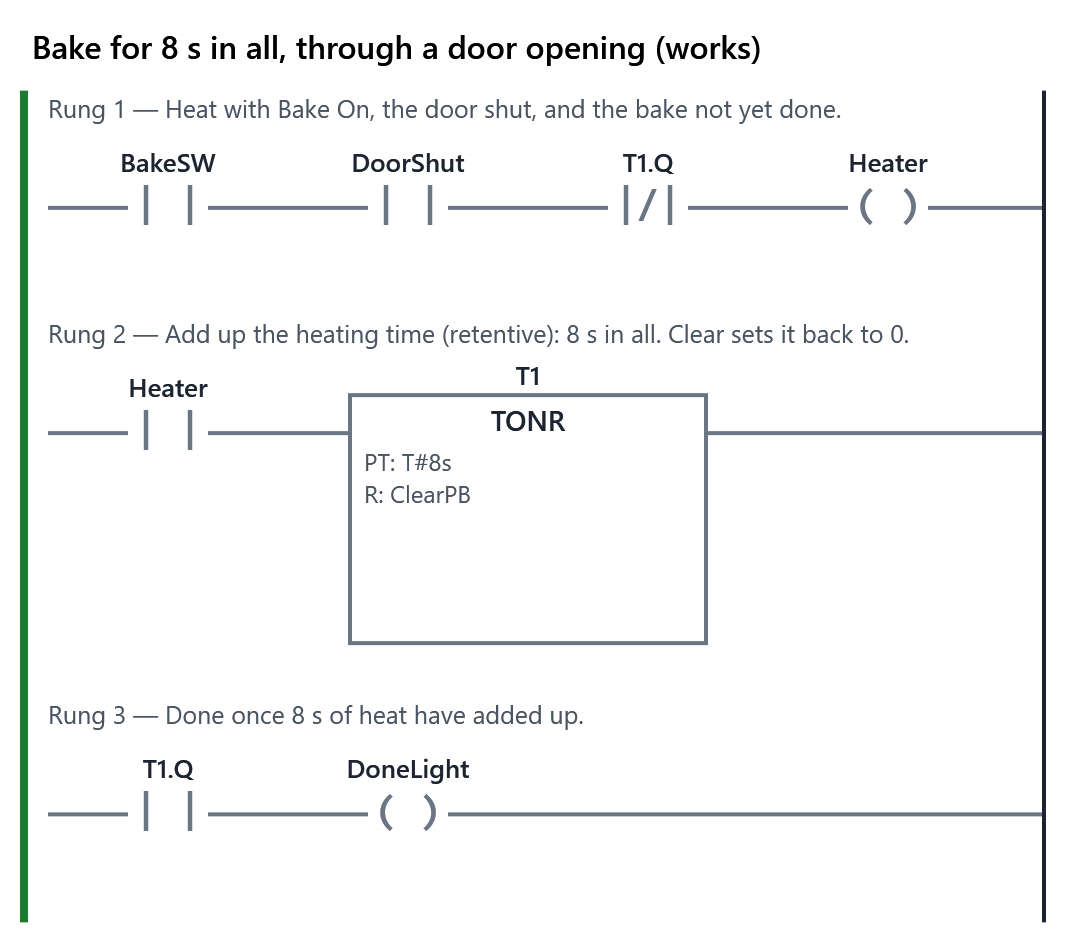
- The machine for “Bake for 8 s in all, through a door opening”, running the working program (also: A common mistake). The working program.
- Exercise
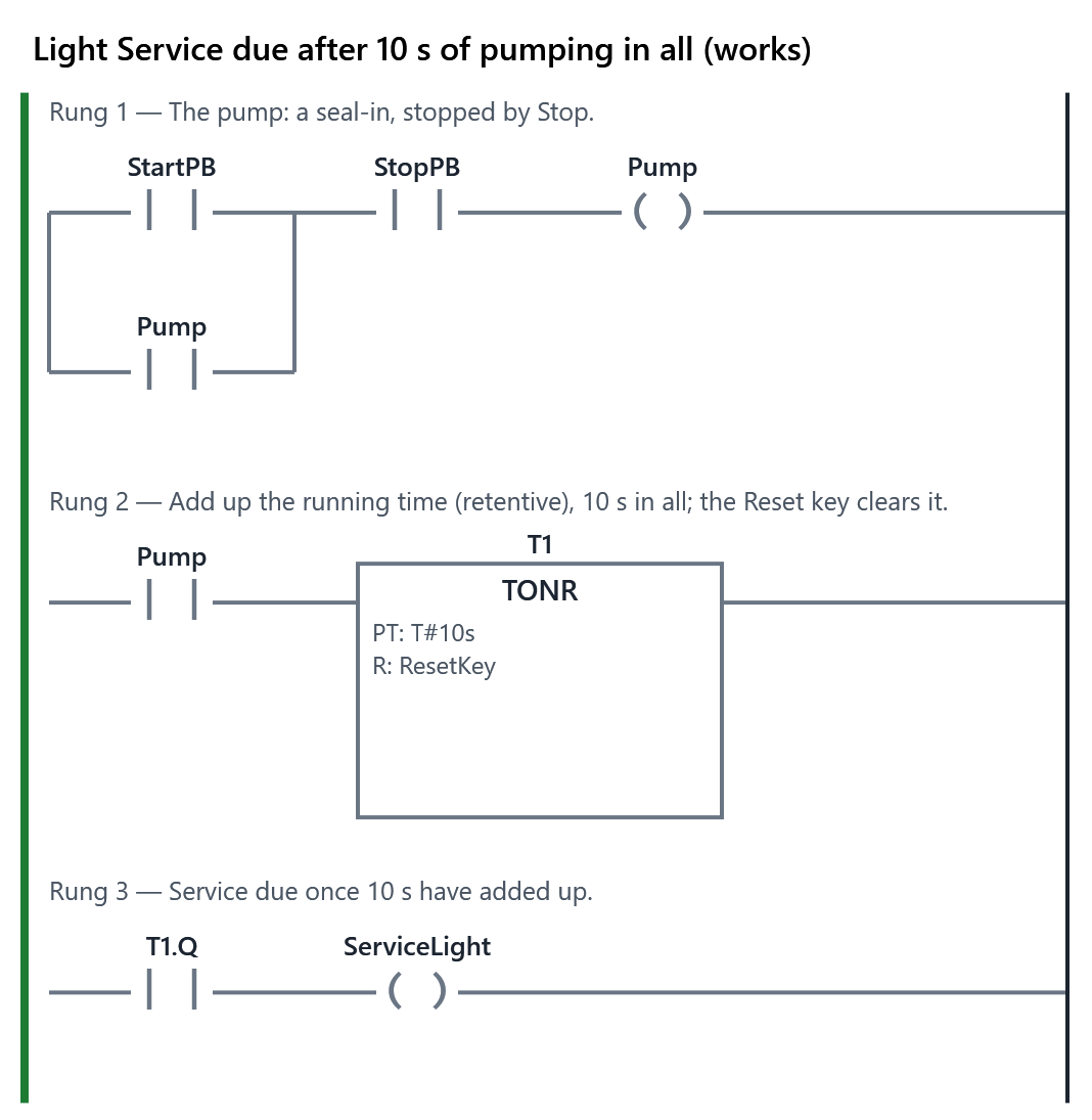
- The learner writes the program for: Start runs the pump and it keeps running; Stop stops it. When the pump has run for 10 s in all, over however many starts, the Service due light comes on, and stays on, even after the pump stops. Turning the Reset key to Reset puts the light out and starts the running time again from 0. (10 s stands in for the hours a real pump would run.) PLC+ checks it with 3 tests (1 hidden). Passing every test completes the item.
- Reference
- Retentive timers (TONR, RTO), Timers
The Learn tab
Retentive timing: a pump's service light
A TON forgets. The moment its IN goes off, ET goes back to 0. That is right for a start-up warning, but some jobs need the time added up over many runs:
- a pump's seals need a service after 500 hours of running, spread over hundreds of starts and stops;
- a part must be baked for 20 minutes in all, even if someone opens the oven door half-way;
- a machine's hour meter must show the total running time.
For these, the timer must keep its time while IN is off, and carry on from there when IN comes back. A timer that keeps its time is called retentive.
The retentive timer, TONR
PLC+ calls it TONR (retentive on-delay); on the Allen-Bradley PLC it is RTO (retentive timer on). It works like a TON with two differences:
- when IN goes off, ET stays where it is; when IN comes back on, ET carries on from there;
- once ET reaches PT, Q turns on and stays on, even when IN goes off.
So nothing in IN can clear it. It has a second input for that: R (reset). While the tag in R is TRUE, ET goes back to 0 and Q goes off.
A TONR with PT T#10s. The pump runs from 0 to 4 s, stops, runs again from 6 s, and stops at 14 s:
| Time | IN | ET | Q |
|---|---|---|---|
| 2 s | TRUE | 2 s | FALSE |
| 4 s | FALSE | 4 s (kept) | FALSE |
| 5 s | FALSE | 4 s | FALSE |
| 6 s | TRUE | 4 s, counting again | FALSE |
| 12 s | TRUE | 10 s | TRUE |
| 14 s | FALSE | 10 s | TRUE (stays on) |
4 s plus 6 s make 10 s, so Q turns on at 12 s. A TON in the same place would have started again from 0 at 6 s, and finished at 16 s, if the pump were still running.
Worked example: an oven that pauses
An oven must bake for 8 s in all. Opening the door turns the heat off, and shutting it carries on where it left off:
- Heater = BakeSW AND DoorShut AND NOT T1.Q: heat with Bake on, the door shut, and the bake not done.
- A TONR, T1, on the Heater, with PT T#8s and ClearPB in R.
- DoneLight = T1.Q.
Open the door at 3 s and shut it at 5 s: T1 holds 3 s while the door is open, and Done lights at 10 s, after 8 s of heat.
When must a timer keep its time?
Ask: if the machine stops part-way, should the time so far still count? A warning horn: no, every start needs the whole warning, so use a TON. Service hours, total baking time, the run time of a batch: yes, so use a TONR, and decide what clears it (a key switch for the maintenance technician, a button for the next batch).
On a real PLC a retentive timer also keeps its time when the PLC is switched off and on again, as long as its tag is retentive memory. That is why RTO is used for hour meters.
Allen-Bradley
RTO has the same .PRE, .ACC, .DN, .EN and .TT as TON. It has no R input on the box: a separate RES (reset) instruction on another rung, naming the same timer tag, clears it. A rung such as XIC ResetKey, RES Pump_Hours does what R does in PLC+.
How to do it
- Open the Example tab: the oven. Turn Bake to On and watch T1's ET count. Turn Oven door to Open part-way: the heater goes off and ET stays put. Shut it again: ET carries on. Done lights after 8 s of heat; press Clear to clear it. Then choose A common mistake in Program, above the machine: it uses a TON. Open the door and watch ET go back to 0.
- Open the Exercise tab: a pump with a Service due light. Write the pump's seal-in first (module 5). Then add Box ▾ ▸ Timers ▸ TONR on a rung of its own, with a contact of Pump before it, PT T#10s, and the right tag in R.
- Press Check my program. One test runs the pump twice, 4 s and then 6 s, and expects Service due at the moment the total reaches 10 s.
Your comments on this item
6.4 Counters: parts in a batch
about 50 minutes · builds on 6.3
- Example
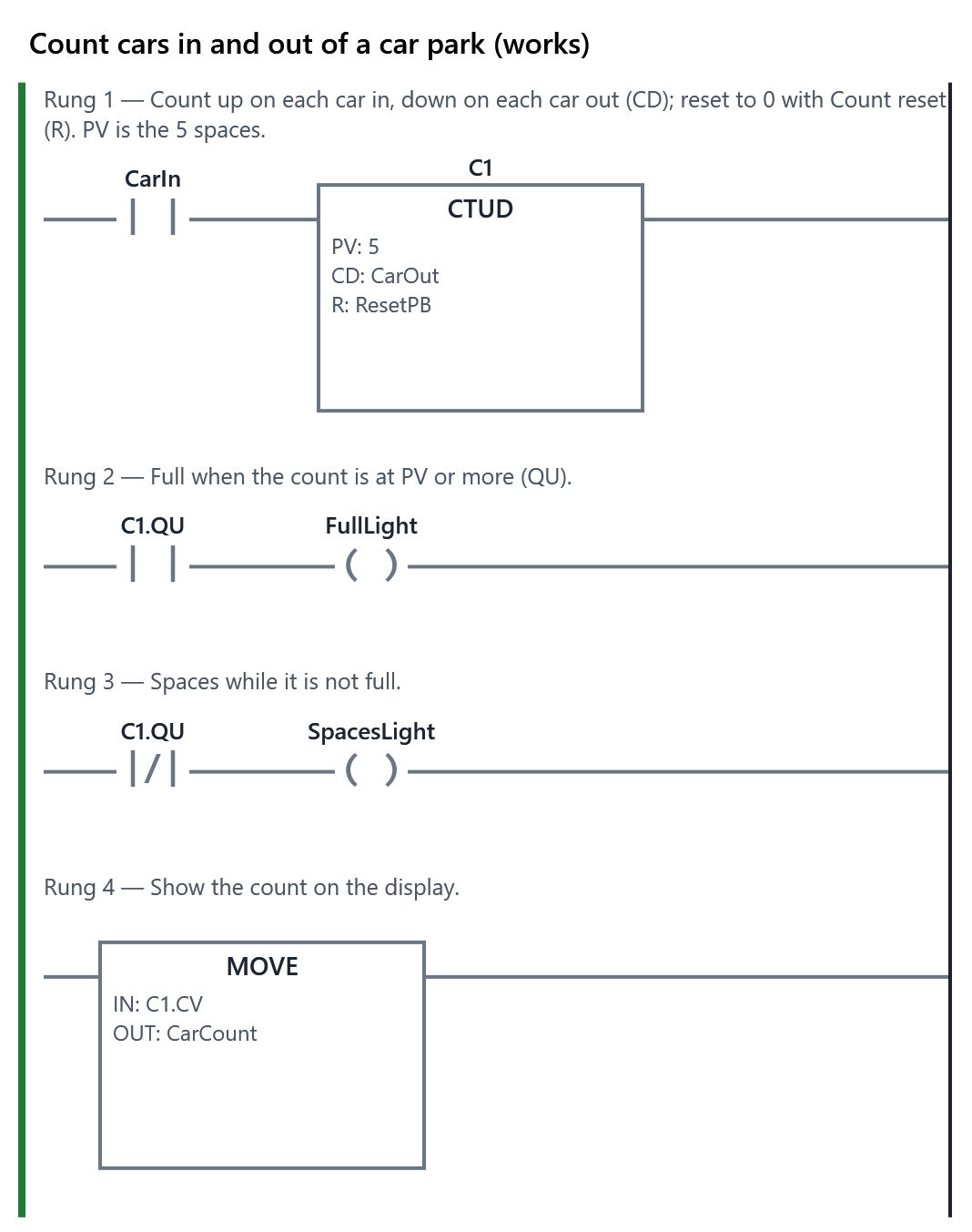
- The machine for “Count cars in and out of a car park”, running the working program (also: A common mistake). The working program.
- Exercise
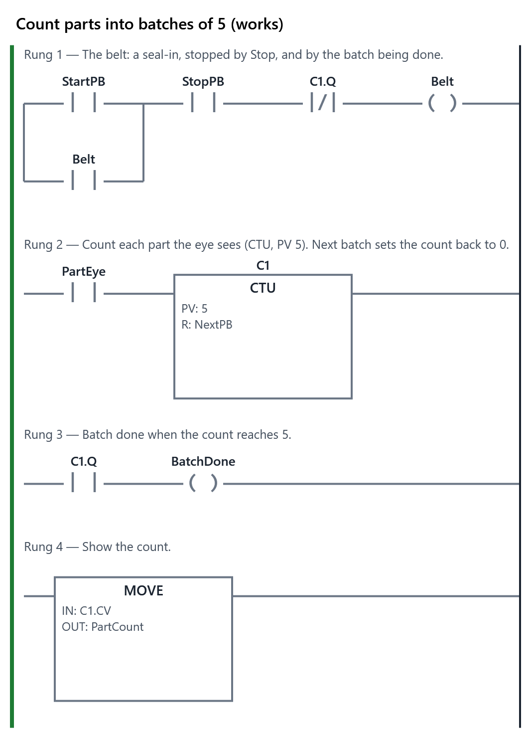
- The learner writes the program for: Start runs the belt and it keeps running; Stop stops it. The photo eye sees each part go by: count them, and show the count on the Parts display. When 5 parts have gone by, the belt stops by itself and Batch done lights. Next batch puts the light out and the count back to 0; then Start runs the belt for the next batch. Stopping the belt part-way through a batch does not lose the count. PLC+ checks it with 4 tests (1 hidden). Passing every test completes the item.
- Reference
- Counters, Edges (one-shots)
The Learn tab
Counters: parts in a batch
A counter is a box that counts how many times its input has turned on: parts past a photo eye, cars through a gate, strokes of a press. It counts edges, not scans: a part that sits in front of the eye for 2 s is still one count, because the counter adds one only at the moment its input goes from FALSE to TRUE (as a -|P|- contact does, module 5).
The up counter, CTU
| Value | What it is |
|---|---|
| CU | the power into the box: each time it turns on, the count goes up by 1 |
| PV | the preset value: the count at which Q turns on, such as 5 |
| R | a tag that sets the count back to 0 while it is TRUE |
| CV | the current value: the count so far, a whole number (INT) |
| Q | TRUE while CV is at least PV |
Two things surprise beginners:
- A counter does not stop at PV. It keeps counting: 6, 7, 8 … and Q stays on. Something must stop the parts, or reset the count.
- A counter does not reset itself, and a stop does not reset it. Its count stays until R clears it. That is what you want for a batch that is stopped part-way: the count carries on when it starts again.
The down counter, CTD
A CTD counts down. Its LD (load) input puts PV into CV; each edge on its input takes 1 off; Q is TRUE when CV is 0 or less. Use it when you think "how many are left": load 12 when a new box arrives, count down as bottles go in, and Q says the box is full.
The up/down counter, CTUD
A CTUD counts both ways: the rung's power counts up, and a tag in its CD input counts down. It has R (to 0) and LD (to PV), and two outputs: QU, TRUE while CV is at least PV, and QD, TRUE while CV is 0 or less.
Worked example: a car park with 5 spaces. Entry sensor CarIn on the rung, exit sensor CarOut in CD, PV 5, a Count reset button in R. Full = C1.QU; Spaces = NOT C1.QU. Five cars in: CV 5, Full. One out: CV 4, Spaces again.
Showing the count
To show a count on a numeric display, copy it there with a MOVE box: IN C1.CV, OUT the display's tag (such as PartCount). A MOVE on a rung with no contacts copies every scan. Module 7 has more on numbers; this is all you need for now.
Allen-Bradley
The lab's PLC has CTU and CTD with a counter tag; its members are .PRE (PV), .ACC (CV), .DN (done), .CU/.CD (the rung is on), and .OV/.UN (it went over or under its range). The counter is cleared by a RES instruction on another rung, as an RTO is. There is no CTUD box: you put a CTU and a CTD on two rungs naming the same counter tag, and both change the same .ACC. Note one difference: Allen-Bradley's .DN is TRUE while .ACC is at least .PRE for both CTU and CTD, unlike the IEC CTD's Q, which is TRUE at zero.
How to do it
- Open the Example tab: the car park. Press Car in five times and watch CV count on the rung and on the Cars inside display; Full lights at 5. Press Car out. Then choose A common mistake in Program, above the machine: nothing is wired to CD, so a car leaving changes nothing.
- Open the Exercise tab: the batch counter. Start the belt and watch the parts pass the photo eye. Write the belt's seal-in (the belt must stop by itself when the batch is done: what does that add to the rung?), then Box ▾ ▸ Counters ▸ CTU with a contact of PartEye before it.
- Add a rung with Box ▾ ▸ Move and bit logic ▸ MOVE to show the count on PartCount, and a rung for Batch done.
- Press Check my program. One of the tests is hidden: it checks a case the brief describes but the visible tests do not.
Your comments on this item
6.5 Cascading timers and counters: a case packer
about 50 minutes · builds on 6.4
- Example
- The machine for “Flash a beacon, and sound the horn after 3 flashes”, running the working program (also: A common mistake). The working program.
- Exercise
- The learner writes the program for: Start runs the belt and it keeps running; Stop stops it. Count the bottles the eye sees: every 6 bottles make a pack, so the Packs display goes up by one and the Bottles display goes back to 0. When 4 packs have been made, the case is full: the belt stops by itself and Case full lights. Case removed sets both counts back to 0 and puts the light out; then Start runs the belt for the next case. PLC+ checks it with 4 tests (1 hidden). Passing every test completes the item.
- Reference
- Cascading timers and counters, Counters, Timers
The Learn tab
Cascading timers and counters: a case packer
One timer measures one stretch of time, and one counter counts one kind of event. Many jobs need more: a light that flashes on and off for ever, a time longer than one timer can hold, or bottles counted into packs and packs into cases. You get them by cascading: one timer's or counter's output drives the next one's input, or resets itself or another.
A flasher from two timers
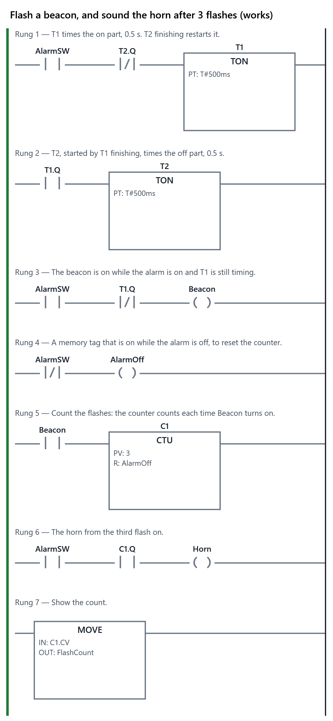
A beacon must flash: on 0.5 s, off 0.5 s, over and over. One TON cannot do it: it times once and then sits at "done". Two can, each starting the other:
- T1 (TON, 0.5 s) on the rung Alarm AND NOT T2.Q: it times the on part.
- T2 (TON, 0.5 s) on the rung T1.Q: when T1 is done, T2 times the off part.
- The beacon is on while Alarm AND NOT T1.Q: on while T1 is timing.
When T2 is done, its normally closed contact breaks T1's rung: T1 resets, so T1.Q goes off, so T2 resets too, and T1 starts again. One round takes 1 s (and a scan or two: PLC+ shows you exactly how many if you step through it).
This is the same trick as the traffic light in 6.1: a chain of timers, the last one restarting the first.
A timer driving a counter
Count the flashes: a CTU on the rung Beacon adds one every time the beacon comes on. With PV 3, its Q can sound a horn from the third flash. The same idea makes long times: a timer that restarts itself every minute, counted by a CTU with PV 60, measures an hour.
A counter driving a counter
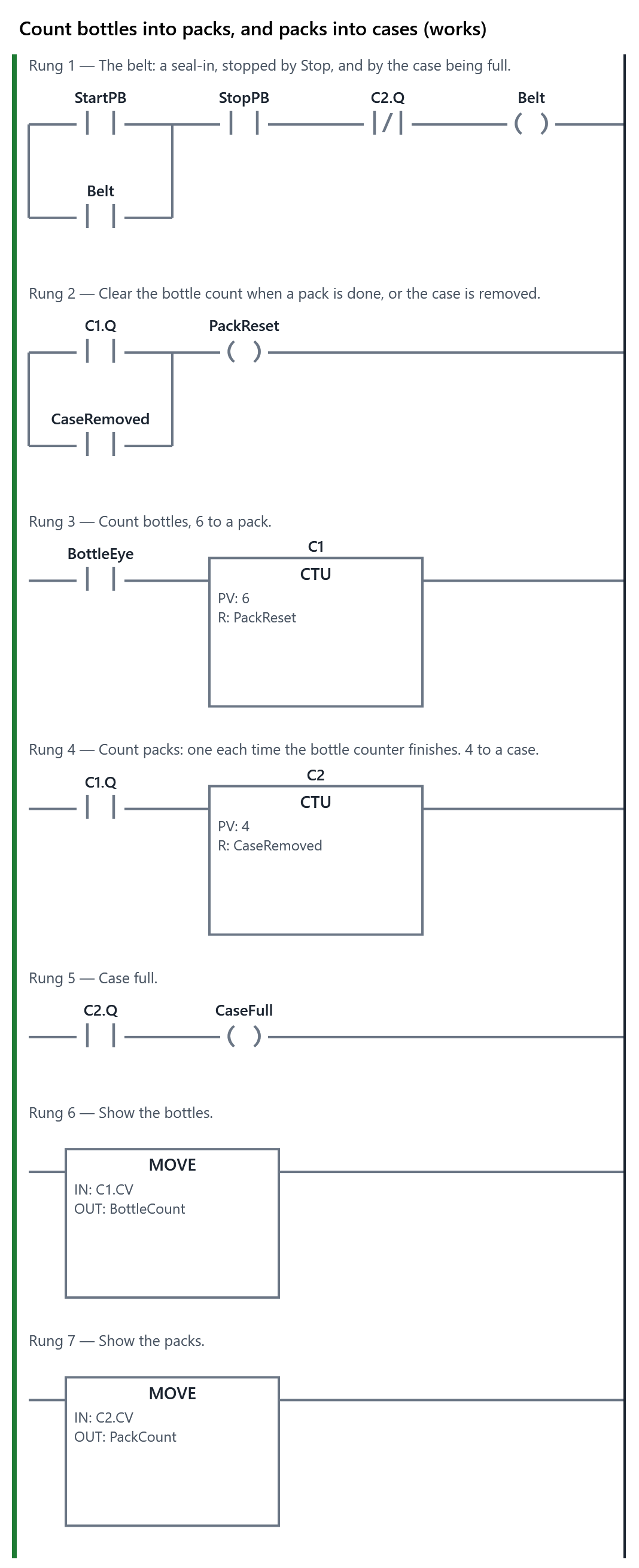
Bottles go into packs of 6, and packs into cases of 4:
| Counter | Counts | PV | Its Q means |
|---|---|---|---|
| C1 | bottles at the eye | 6 | a pack is complete |
| C2 | each time C1.Q comes on | 4 | the case is full |
For C2 to count every pack, C1 must start again from 0 after each one. So C1.Q must reset C1: put a tag in C1's R that comes on when C1.Q does. In the scan after C1 reaches 6, R clears it, C1.Q goes off, and C2 has seen exactly one rising edge. C1.Q is TRUE for one scan per pack: a one-shot made by the counter itself.
R takes one tag, so if C1 must also be cleared by a button, make a memory tag from a branch: PackReset = C1.Q OR CaseRemoved, and put PackReset in R.
Watch the order of the rungs
In cascades, which rung comes first matters by one scan (10 ms). A contact of C1.Q on a rung above C1's box sees the value from the last scan; on a rung below it, the value from this scan. That is rarely a problem, but it is why a one-scan pulse can be missed by a rung that reads it before it is made, and then cleared. If a cascade does not work, step through it one scan at a time.
Allen-Bradley
The same patterns work with .DN: XIO T2.DN on T1's rung for the flasher; XIC Bottles.DN as the rung of the pack counter's CTU; and a rung XIC Bottles.DN, RES Bottles to clear the bottle counter. On the lab's PLC the .DN of a counter stays on until RES, so the RES rung is needed there too.
How to do it
- Open the Example tab: the alarm beacon. Turn Alarm to On and watch T1 and T2 take turns, and the Flashes display count. The horn joins in at the third flash. Press Pause and Step one scan around the moment T2 finishes to see T1 and T2 reset. Then choose A common mistake in Program, above the machine: one timer that resets itself. The beacon looks on all the time: it is off for one scan in every 0.5 s.
- Open the Exercise tab: the case packer. Start the belt and watch the bottles pass the eye. You need two CTUs, the belt's seal-in, and a MOVE for each display. Ask yourself: what should stop the belt? And the bottle counter must be cleared for two different reasons: which, and how can one R input take both? The section above shows a way.
- Press Check my program. A full case takes 24 bottles, about 12.5 s of test time.
Your comments on this item
6.6 Module check
about 20 minutes
- Module check
- Complete when every item it covers is: 6.1, 6.2, 6.3, 6.4, 6.5. Its questions, on the Exercise tab, are below; it is complete when those items are and the questions are passed. Once it is complete, the learner makes the PDF progress report to hand in (Hand in a report).
The Learn tab
Module check: timers and counters
This check covers the five exercises of module 6: the traffic light, the exhaust fan, the pump's service light, the batch counter and the case packer. Each is complete when its program passes every test on the Exercise tab.
The check itself is ten questions, on the Exercise tab. Several ask when something happens: picture the timer's IN, ET and Q against time, as in the tables on the Learn pages, and type the answer in seconds. Two are find the fault: a machine from this module's Example tabs runs its working program, but one of its devices or wires is faulty. Work the machine, watch the timers and counters on the rungs, and say what is wrong. You need 80 % to pass, and you can try again.
When all five exercises pass and you have passed the questions, the module is complete and ready to hand in: Hand in a report (the second row of the path) makes the PDF progress report for your instructor, with your score on each exercise and a picture of each program.
The questions (on the Exercise tab)
10 questions; the learner needs 80 % to pass and can try again. A wrong answer says “not quite, look again”; the reason is shown once the answer is right. The right answers are marked ✓ here only.
A number. An on-delay timer (TON) has PT T#3s. Its IN turns on at 2 s and stays on. At what time does its Q turn on?
✓ 5 s (within 0)
Why: Q turns on when IN has been on for PT: 2 s + 3 s = 5 s.
A number. An off-delay timer (TOF) has PT T#5s. Its IN turns on at 1 s and off at 4 s. At what time does its Q turn off?
✓ 9 s (within 0)
Why: A TOF's Q is on while IN is on, and for PT after IN goes off: 4 s + 5 s = 9 s. The time IN was on does not matter.
Choose one. A pulse timer (TP) has PT T#2s. Its IN turns on at 0 s and is held on until 6 s. When is its Q on?
- ✓ From 0 s to 2 s; then off, although IN is still on
- From 0 s to 6 s; Q follows IN for as long as IN is held
- From 2 s to 6 s; Q waits PT, then stays on while IN is on
- From 0 s to 8 s; Q stays on for 2 s after IN goes off
Why: A pulse timer gives one pulse of exactly PT from the moment IN turns on, whatever IN does during it. On until 6 s would be IN itself; from 2 s would be a TON; until 8 s would be a TOF.
Find the fault: a machine with a faulty wire, running the working program. This conveyor runs the working program from the Example in 6.1, but one device is faulty. Press Start, and watch the horn, the motor and the rungs for 4 s. Which fault does it have?
Machine: Warn for 3 s, then start the conveyor; the fault:
WarnHorn:failed- ✓ The horn has failed: the PLC turns WarnHorn on for 3 s, but the horn does not sound
- The motor has failed: the PLC turns Motor on after 3 s, but the belt does not move
- The wire to Start is broken: Start always reads FALSE, so RunRequest never seals in
- The wire to Stop is broken: Stop always reads FALSE, so RunRequest drops at once
Why: On the rungs everything is right: RunRequest seals in, T1 counts to 3 s, WarnHorn is TRUE for those 3 s, and then the motor starts. Only the horn itself stays quiet, so the program is fine and the device (or its wiring) has failed. A broken Start or Stop wire would keep anything from starting. On a real conveyor, nobody would be warned: fix it before running the belt.
A number. A retentive timer (TONR; RTO on Allen-Bradley) has PT T#10s, and nothing turns on its R. Its IN is on from 0 s to 4 s, off from 4 s to 7 s, and on again from 7 s. At what time does its Q turn on?
✓ 13 s (within 0)
Why: It keeps the 4 s while IN is off, and carries on from 7 s: it needs 6 s more, so Q turns on at 7 s + 6 s = 13 s. A TON would have started again from 0 at 7 s and finished at 17 s.
Choose every one that is right. Which of these jobs need a retentive timer, one that keeps its time while its input is off? Choose every one.
- ✓ A Service due light after a pump has run 500 hours in all, over many starts
- A horn that sounds for 3 s before a conveyor starts, every time it starts
- ✓ A part that must bake for 20 minutes in all, even if the oven door is opened part-way
- A fan that runs on for 5 s after a heater turns off
- ✓ An hour meter showing a machine's total running time
Why: Each of these adds time up over several runs, so the time must survive a stop: a TONR (RTO), cleared on purpose by its R input (RES on Allen-Bradley). The start-up warning must be the full 3 s every time (a TON), and the fan's run-on is an off-delay (a TOF).
Choose one. An up counter (CTU) has PV 5 and nothing in its R. A photo eye on its rung sees 7 parts go by. What do its CV and Q show?
- ✓ CV is 7 and Q is TRUE: it counts past PV, and Q is on from 5
- CV is 5 and Q is TRUE: it stops counting when it reaches PV
- CV is 2 and Q is FALSE: it starts again from 0 at PV
- CV is 7 and Q is FALSE: Q is on only when CV equals PV
Why: A counter keeps counting past PV, and Q is TRUE while CV is at least PV. Only R sets it back to 0, so a program must reset it, or stop the parts, itself.
Find the fault: a machine with a faulty wire, running the working program. This car park runs the working program from the Example in 6.4, but one input is faulty. Press Car in five times, then Car out, and watch the display and the counter's rung. Which fault does it have?
Machine: Count cars in and out of a car park; the fault:
CarOut:open- ✓ The exit sensor's wire is broken: CarOut always reads FALSE, so cars leaving are never counted
- The entry sensor is shorted: CarIn always reads TRUE, so the count never goes up
- The Full light has failed: the PLC turns Full on at 5, but the light stays dark
- The Reset button is shorted: ResetPB always reads TRUE, so the count stays at 0
Why: Cars in count up to 5 and Full lights at 5, so the entry sensor, PV and the light are fine. Car out changes nothing: on the rung CarOut never turns TRUE, so CD never sees an edge.
A number. In the case packer, C1 counts bottles (PV 6) and is cleared each time it finishes; C2 counts each time C1 finishes (PV 4). Since the case was started, the displays show Packs 2 and Bottles 5. How many bottles have passed the eye since the case was started?
✓ 17 bottles (within 0)
Why: Each pack is 6 bottles, so 2 packs are 12, and 5 more make 17.
Choose one. In the alarm beacon of 6.5, T1 (a TON, 0.5 s) times the beacon's on part, and T2 (a TON, 0.5 s, started by T1.Q) times the off part. What makes T1 start timing again after the off part?
- ✓ A normally closed contact of T2.Q on T1's rung: when T2 is done it breaks the rung, T1 resets, and T2 resets in turn
- Nothing on the rungs: a TON resets itself when its ET reaches PT, and T1 starts again from 0
- A normally closed contact of the Beacon on T1's rung: when the beacon goes off, T1 resets
- The flash counter's Q in T1's R input: each counted flash clears T1, and it starts again
Why: A TON stays done while its IN is on; it resets only when IN goes off. T2 finishing turns T1's IN off for a scan, which resets T1, which resets T2, which lets T1 start again.