← The review guideReference pages
Module 8 · Sequencing and state machines
First draft, for your review · about 4.5 hours
Recommended first
Module 6, Timers and counters (recommended, not enforced)
What the learner will be able to do
- Program a machine as a sequence of steps, one memory bit per step, each step moving on only when a sensor says the step before has finished. (plc.m8.o1)
- Design a state machine (named states, the moves between them and their conditions, a stop or fault state and the way back to idle), and read an introductory SFC chart. (plc.m8.o2)
- Run a sequence from a step number (an INT tag), with compare instructions choosing the outputs and MOVE choosing the next step. (plc.m8.o3)
Topics
Step logic · Sequencers with a step number · State machines · Introduction to SFC
About this module
Most machines do things in an order: clamp the part, stamp it, let it go; fill the tank, mix it, drain it. Each part of the order is a step, and the program's job is to know which step the machine is in and to move on only when the machine says that step is done.
This module gives you three ways to write that, from the simplest to the most flexible: one memory bit per step (step logic), one number for the step (a sequencer), and a state machine, where the machine can move from one state to several others, stop in the middle and find its way back. The last item reads a Sequential Function Chart (SFC), the IEC 61131-3 language drawn as steps and transitions, and shows how a chart becomes ladder.
The machines are new too: air cylinders that take time to move and tell the PLC when they have arrived. As in module 5, each item has a working Example on one machine and an Exercise on another. You will use seal-ins and set/reset coils (module 5) and on-delay timers (module 6).
The items
Each item has four tabs in PLC+: Learn (the lesson below), Example (a machine running a working program), Exercise (the learner writes the program; PLC+ checks it) and Reference. Every item has a comment box under it.
- 8.1 Step logic: a stamping station
- 8.2 Sequencers with a step number: a batch tank
- 8.3 State machines: a gate that can stop anywhere
- 8.4 An introduction to SFC (Sequential Function Chart)
- 8.5 Module check
8.1 Step logic: a stamping station
about 60 minutes
- Example
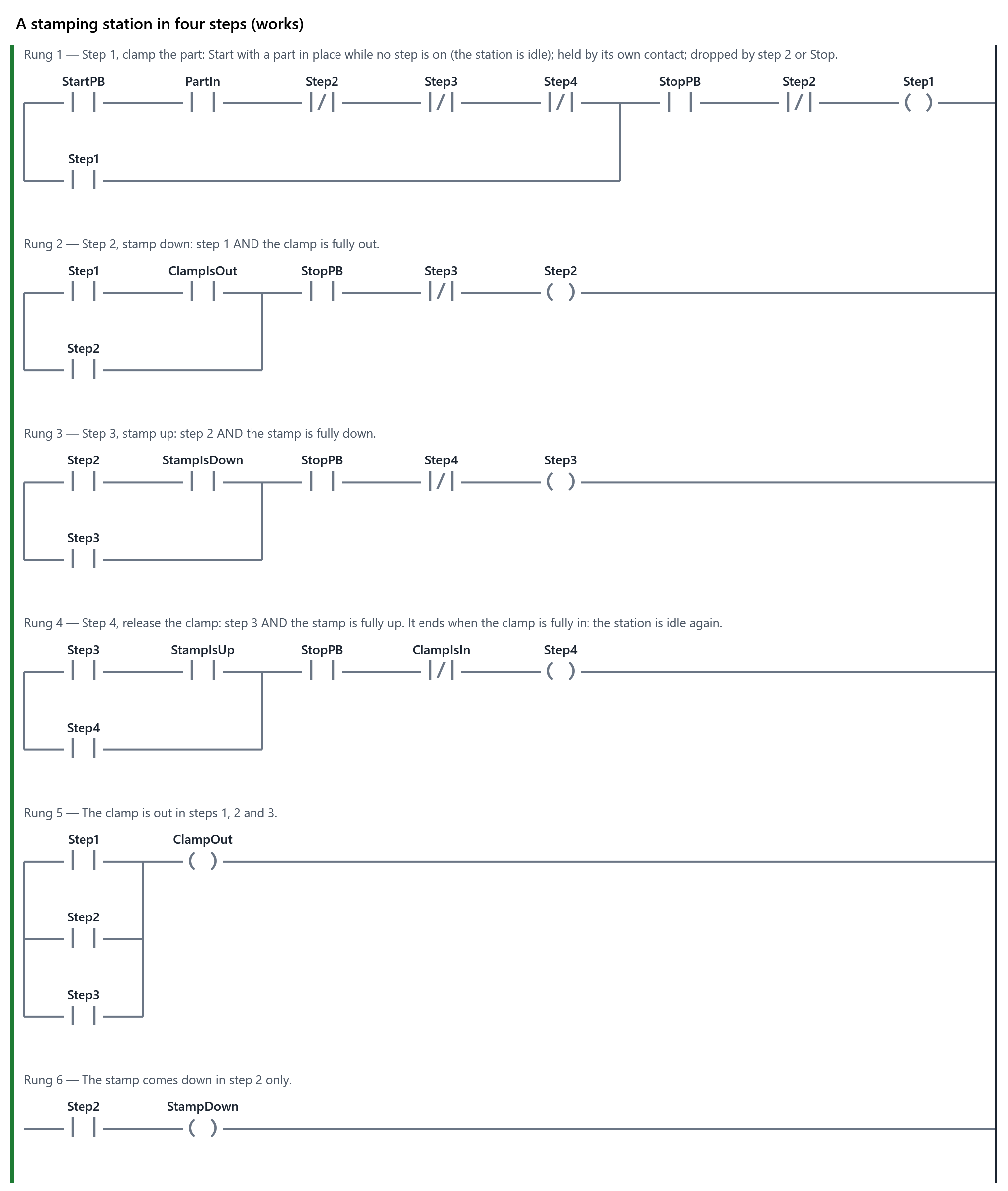
- The machine for “A transfer arm in four steps”, running the working program (also: A common mistake). The working program.
- Exercise
- The learner writes the program for: Turn Part in place to Part in and press Start. The station then works through four steps, each one starting only when the step before has finished: 1. the clamp extends and holds the part, until ClampIsOut says it is fully out; 2. the stamp comes down, until StampIsDown; 3. the stamp goes back up, until StampIsUp; 4. the clamp lets go, until ClampIsIn. Then the station is idle, ready for the next part. Start does nothing without a part, or while a cycle is running. Stop ends the cycle at once: every step ends, both cylinders spring back, and the next Start begins a new cycle. Stop is wired normally closed. Each cylinder has one solenoid: it extends while its output (ClampOut, StampDown) is on. PLC+ checks it with 4 tests (1 hidden). Passing every test completes the item.
- Reference
- Step logic (one bit per step), The seal-in (holding) circuit, Set and reset coils (latching)
The Learn tab
Step logic: a stamping station
A stamping station puts a mark on a part, always in the same order: clamp the part, bring the stamp down, lift the stamp, let the part go. Each of these is a step. The program must know which step the machine is in, and move to the next step only when the machine says the step is finished.
Air cylinders take time
The clamp and the stamp are air cylinders: a rod that slides out when air is let in. A solenoid (an electric valve) lets the air in; the PLC turns it on with an output.
- A cylinder with one solenoid extends while its output is on, and a spring pulls it back when the output is off.
- A cylinder with two solenoids has one to push it out and one to pull it in. With neither on, it stays where it is.
- Two sensors on the cylinder say when it is fully out and fully in.
A cylinder takes time to move: the stamping station's clamp takes half a second. So the program must not bring the stamp down just because it told the clamp to go out. It waits for the fully out sensor, ClampIsOut: that is the machine saying "done".
One memory bit per step
Give each step a memory tag of its own: Step1, Step2, Step3, Step4. Exactly one is on while the machine works, and none while it is idle. Each step's rung is a seal-in (module 5):
- a step starts when the step before it is on AND the sensor says the step before has finished;
- it holds itself on with its own contact, in parallel;
- it ends when the next step starts: a normally closed contact of the next step, in series. Stop ends it too.
For the transfer arm on the Example tab, step 2 (arm out) starts when step 1 (grip) is on and the gripper is fully closed:
(Step1 AND GripIsClosed) OR Step2, then StopPB, then NOT Step3, to the Step2 coil.
The first step starts from Start, but only when no step is on. The last step ends when its own sensor says it has finished (the arm is fully in), and the machine is idle again.
The outputs come last
Write the outputs in rungs of their own, after the steps, one rung per output. Where an output is on in more than one step, put those steps side by side in a branch (OR). The gripper holds the part in steps 1 and 2: Step1 OR Step2 drives GripClose.
The worked example
| Step | What moves | It has finished when |
|---|---|---|
| 1 Grip | GripClose on | GripIsClosed |
| 2 Arm out | GripClose and ArmOut on | ArmIsOut |
| 3 Let go | everything off: the gripper springs open | GripIsOpen |
| 4 Arm back | ArmIn on | ArmIsIn: the cycle is over |
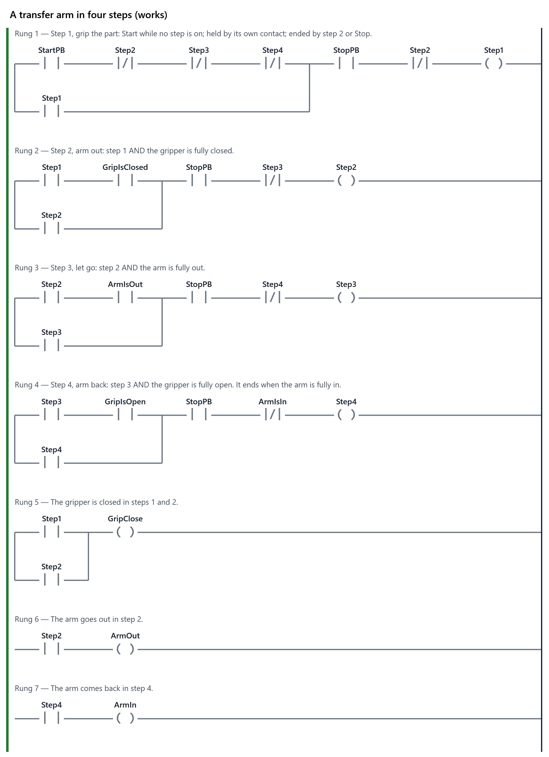
With set and reset coils (OTL and OTU on Allen-Bradley) the same idea is: step 1 AND GripIsClosed sets Step2, and Step2 resets Step1. Either way works; just never leave a step without something to end it.
How to do it
- Open the Example tab: the transfer arm. Press Start and watch Step1 to Step4 take turns on the rungs while the cylinders move. Use Pause and Step one scan at the moment a sensor turns on to see the next step start and the one before end in the next scan. Then choose A common mistake in Program, above the machine: nothing ends step 1. Where does the arm stop, and why?
- Open the Exercise tab: the stamping station. Write down its four steps first, as in the table above: what moves, and which sensor says it has finished.
- Write one rung per step: type Step1 on a coil and PLC+ declares it. Use Branch for the seal-in. Then one rung per output.
- Turn Part in place to Part in, press Start, and watch. Then press Check my program. One test is hidden: it checks something the brief asks for that the visible tests do not.
Your comments on this item
8.2 Sequencers with a step number: a batch tank
about 60 minutes · builds on 8.1
- Example
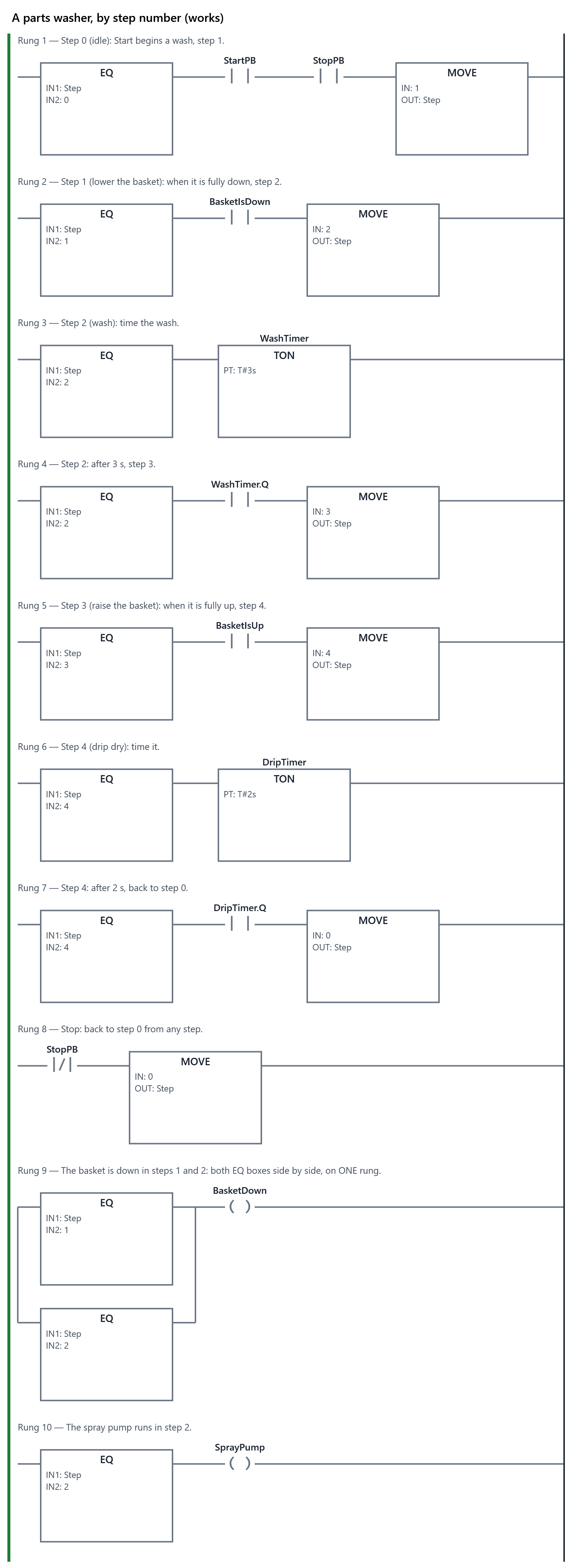
- The machine for “A parts washer, by step number”, running the working program (also: A common mistake, Written as an SFC). The working program.
- Exercise
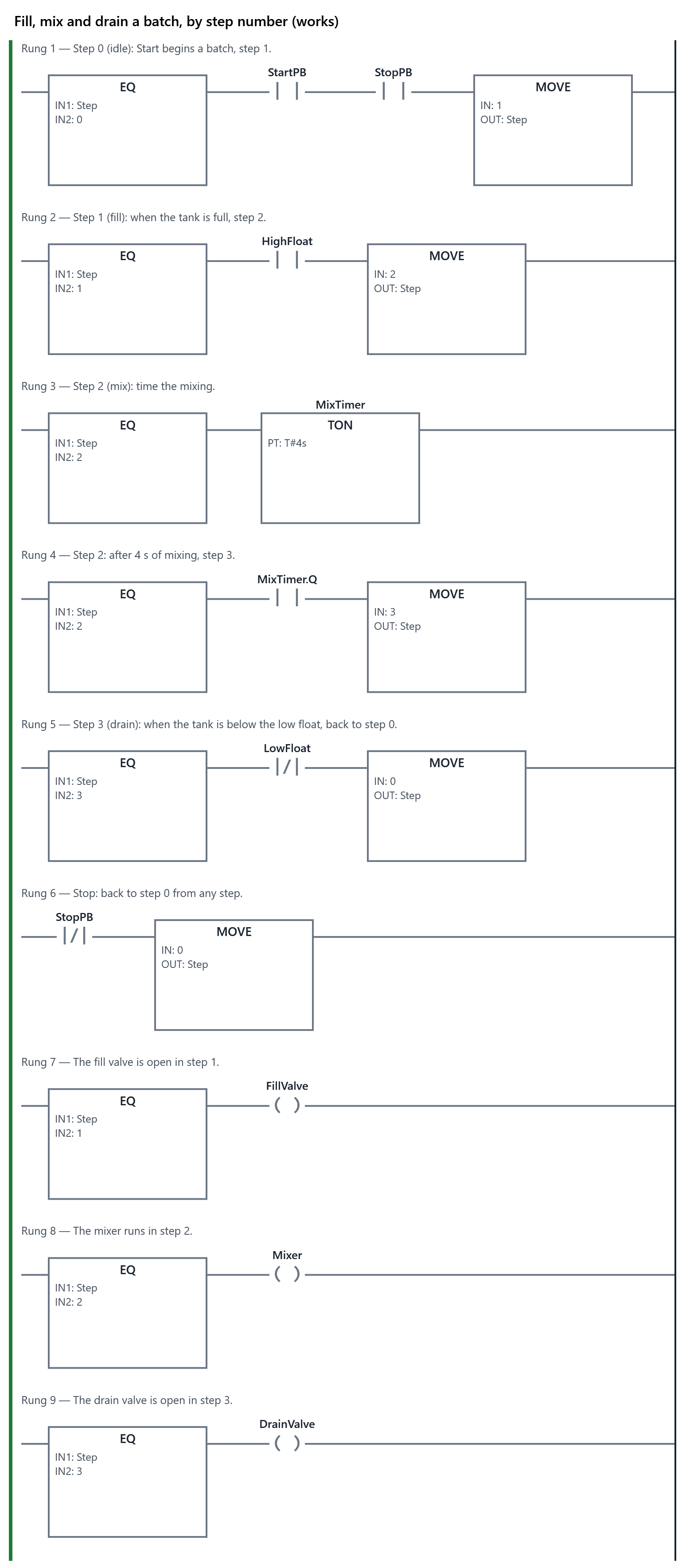
- The learner writes the program for: Run the batch from a step number, an INT tag called Step (the Step display shows it). Step 0 is idle: nothing on. Start in step 0 begins a batch. Step 1 fills: the fill valve is open until the high float (80 %), then step 2. Step 2 mixes: the mixer runs for 4 s, then step 3. Step 3 drains: the drain valve is open until the level is below the low float (10 %), then back to step 0. Start does nothing in steps 1, 2 and 3. Stop goes back to step 0 from any step, and everything stops. Stop is wired normally closed. PLC+ checks it with 4 tests (1 hidden). Passing every test completes the item.
- Reference
- Sequencers with a step number, Timers
The Learn tab
Sequencers with a step number: a batch tank
A memory bit per step works well for four steps. With twenty, there are twenty bits to keep straight. The other common way is one number for the whole sequence: an INT tag, here called Step, that holds the number of the step the machine is in. Step 0 is idle; step 1 is the first step, and so on. An operator can read it on a display: "Step 2" says exactly where the machine is.
Two boxes do the work
- EQ (compare equal; EQU on Allen-Bradley) passes power when IN1 equals IN2. With IN1 = Step and IN2 = 2, it passes power only in step 2. It works like a contact that asks "are we in step 2?".
- MOVE (MOV on Allen-Bradley) copies IN into OUT while power reaches it. With IN = 3 and OUT = Step, it moves the machine to step 3.
Outputs: one EQ each
Each output's rung is an EQ box for its step, then the coil: EQ Step 1 then the FillValve coil. If an output is on in two steps, put two EQ boxes side by side (a branch) on one rung. Never write two rungs with coils of the same tag: the PLC runs both, and the lower one decides. The Example's common mistake shows what that does.
Moving on: EQ, the condition, MOVE
Each move to the next step is a rung of three parts: an EQ box for the step it leaves, the condition that says that step has finished, and a MOVE of the next number into Step:
EQ Step 1, HighFloat, MOVE 2 to Step: "in step 1, when the tank is full, go to step 2."
There is nothing to end: when Step changes, the step before is over, because Step can hold only one number. The rungs below see the new number in the same scan.
- A step that waits for a time: a TON on a rung of its own, powered by EQ Step 2. The next rung moves on when its .Q turns on. When the step ends, the timer's input goes off and it resets, ready for the next batch.
- Start belongs to step 0 only: EQ Step 0, StartPB, MOVE 1.
- Stop works in every step, so its rung has no EQ box: NOT StopPB, MOVE 0. Put it after the other moves, so it has the last word.
The worked example: a parts washer
| Step | Outputs on | Moves on when | To |
|---|---|---|---|
| 0 Idle | none | Start | 1 |
| 1 Lower the basket | BasketDown | BasketIsDown | 2 |
| 2 Wash | BasketDown, SprayPump | WashTimer.Q (3 s) | 3 |
| 3 Raise the basket | none (the spring lifts it) | BasketIsUp | 4 |
| 4 Drip dry | none | DripTimer.Q (2 s) | 0 |
Many plants number steps 10, 20, 30 instead of 1, 2, 3, so that a step added later can be 15 without renumbering the rest. Allen-Bradley PLCs also have a sequencer instruction, SQO, that steps through a table of output patterns; PLC+ does not have it, and the step number with EQ and MOVE works on every PLC.
How to do it
- Open the Example tab: the parts washer. Press Start and watch the Step display count 1, 2, 3, 4 and back to 0, and the EQ boxes pass power one at a time. Then choose A common mistake in Program, above the machine: BasketDown has two rungs. Press Start, and watch which rung turns it off.
- Open the Exercise tab: the batch tank. Fill the tank to the high float, mix for 4 s, drain it below the low float. Write the table first.
- Add a box with Box ▾ ▸ Compare ▸ EQ and Box ▾ ▸ Move and bit logic ▸ MOVE. Type the values in the box's IN1, IN2, IN and OUT boxes above the rungs and press Enter. Step is already declared, as an INT, because it drives the display. The mixing time is Box ▾ ▸ Timers ▸ TON. In My program your timers are called T1, T2 … (PLC+ cannot rename them yet), so where the Example reads WashTimer.Q, yours reads T1.Q.
- Press Check my program. One test is hidden. Try pressing Start in the middle of a batch: what should happen?
Your comments on this item
8.3 State machines: a gate that can stop anywhere
about 70 minutes · builds on 8.2
- Example
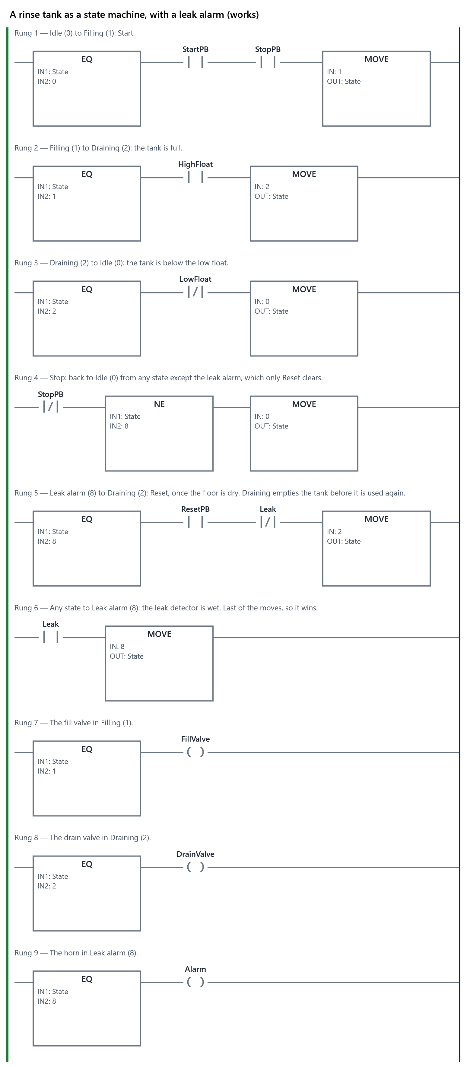
- The machine for “A rinse tank as a state machine, with a leak alarm”, running the working program (also: A common mistake). The working program.
- Exercise
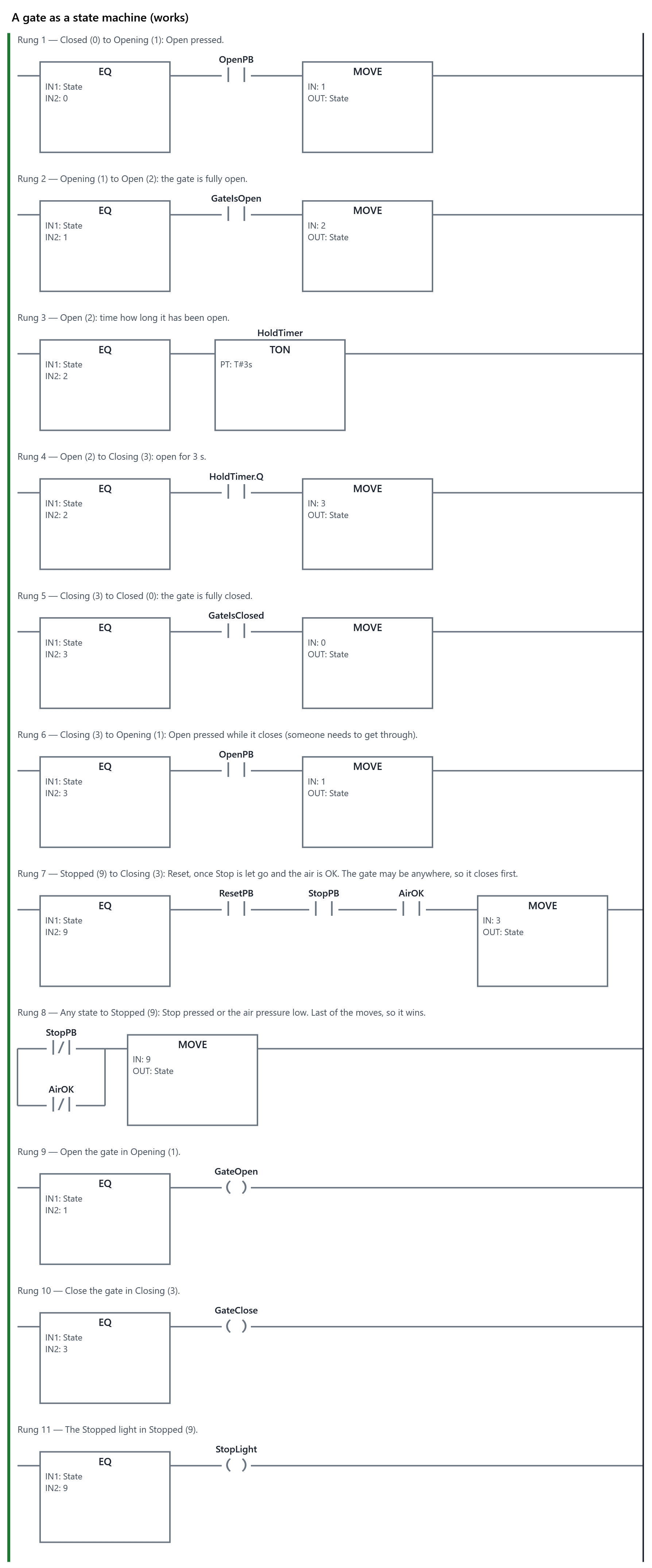
- The learner writes the program for: Write the gate as a state machine, with its state number in the INT tag State (the State display shows it). States: 0 Closed (nothing on), 1 Opening (GateOpen on), 2 Open (nothing on; it waits 3 s), 3 Closing (GateClose on), 9 Stopped (the Stopped light on, nothing moves). Moves: Closed to Opening when Open is pressed; Opening to Open when GateIsOpen; Open to Closing after 3 s; Closing to Closed when GateIsClosed; Closing to Opening when Open is pressed (someone needs to get through). From ANY state to Stopped when Stop is pressed or the air pressure is low. Stopped to Closing when Reset is pressed, but only once Stop is let go and the air pressure is OK: the gate may have stopped anywhere, so it closes before the machine is idle again. Stop is wired normally closed; AirOK is TRUE while the pressure is OK. PLC+ checks it with 4 tests (1 hidden). Passing every test completes the item.
- Reference
- State machines, Sequencers with a step number, Timers
The Learn tab
State machines: a gate that can stop anywhere
A sequence goes 1, 2, 3, 4 and round again. Real machines are not that tidy. An automatic gate is closing when a car arrives: it must open again. Someone presses Stop with the gate half open. The air pressure drops. A state machine handles all of this with three ideas:
- States. The machine is always in exactly one state, and each state has a name that says what the machine is doing: Closed, Opening, Open, Closing, Stopped. A state decides which outputs are on.
- Transitions (moves). Each one goes from one state to another, when a condition is true. A state may have several ways out.
- A stop or fault state, entered from any state, and one planned way back to idle.
Design it as a table first
Before any ladder, write two tables. They are the design; the program is a copy of them. These are the gate's.
| State | Number | Outputs on |
|---|---|---|
| Closed (idle) | 0 | none |
| Opening | 1 | GateOpen |
| Open | 2 | none: the cylinder stays out; a 3 s timer runs |
| Closing | 3 | GateClose |
| Stopped | 9 | the Stopped light |
| From | To | When |
|---|---|---|
| Closed | Opening | Open pressed |
| Opening | Open | GateIsOpen |
| Open | Closing | open for 3 s |
| Closing | Closed | GateIsClosed |
| Closing | Opening | Open pressed |
| any state | Stopped | Stop pressed, or the air pressure low |
| Stopped | Closing | Reset, with Stop let go and the air OK |
Check the tables with questions: can every state be left? Is there a way back to idle from every state? What does each state assume about the machine? Closed assumes the gate is closed. After a stop the gate could be anywhere, so Reset goes to Closing, not straight to Closed; the gate closes first, and only then is the machine idle.
From the tables to ladder
Keep the state as a number in an INT tag, State, as in item 8.2. Write the number's name in the tag's comment and in each rung's comment, so the next person can read it.
- One rung per transition: EQ for the state it leaves, the condition, MOVE the new number. EQ State 3, OpenPB, MOVE 1 to State.
- "From any state" has no EQ box: NOT StopPB OR NOT AirOK, MOVE 9 to State. Put it after the other transitions, so if two happen in the same scan, the stop wins.
- One rung per output, an EQ for each state that turns it on.
- A state machine starts in state 0 when the PLC starts, because an INT starts at 0: make 0 the safe, idle state.
The worked example: a rinse tank with a leak alarm
| From | To | When |
|---|---|---|
| Idle (0) | Filling (1) | Start |
| Filling (1) | Draining (2) | the high float |
| Draining (2) | Idle (0) | below the low float |
| Filling or Draining | Idle (0) | Stop |
| any state | Leak alarm (8) | the leak detector is wet |
| Leak alarm (8) | Draining (2) | Alarm reset, with the floor dry |
The leak alarm is a state, not just a light. It stays until a person presses Alarm reset, even after the floor dries, and it leaves by draining the tank, the safe way back to idle.
How to do it
- Open the Example tab: the rinse tank. Press Start; while it fills, turn the Leak detector to Wet, then back to Dry. The State display stays at 8 until you press Alarm reset. Then choose A common mistake in Program, above the machine: it has no leak state. Try the same, and see what happens when the floor dries.
- Open the Exercise tab: the gate. Its tables are above; write one rung per transition, then one per output. Add the 3 s TON (Box ▾ ▸ Timers ▸ TON) on a rung powered by EQ State 2. My program calls it T1 (PLC+ cannot rename timers yet), so the move from Open to Closing reads T1.Q.
- Try every row of the transition table on the machine: Open; Open again while it closes; Stop halfway; Reset; the Air pressure switch. Then press Check my program. One test is hidden.
Your comments on this item
8.4 An introduction to SFC (Sequential Function Chart)
about 40 minutes · builds on 8.3
- Example
- The machine for “A parts washer, by step number”, running the working program (also: A common mistake, Written as an SFC). The working program.
- Exercise
- Practice questions (below). Passing them completes the item.
- Reference
- Sequential Function Chart (SFC), Step logic (one bit per step)
The Learn tab
An introduction to SFC (Sequential Function Chart)
IEC 61131-3, the standard for PLC languages, has a language made for sequences: the Sequential Function Chart, or SFC. Instead of rungs, you draw the sequence itself: boxes for the steps, and a short bar between them for each condition. Allen-Bradley ControlLogix and CompactLogix PLCs have an SFC editor in Studio 5000, and so do most other makers' tools.
PLC+ has no SFC editor yet: it is planned for a later version. This item teaches you to read a chart, and shows how each part of it becomes the ladder you already write.
The parts of a chart
- A step is a box with a name, such as S2. While the machine is in that step, the step is active. In Studio 5000 each step has a tag; S2.X is TRUE while it is active, and S2.T is how long it has been active.
- The initial step has a double border. It is active when the PLC starts: the idle step.
- A transition is a short bar across the line from one step to the next, with its condition written beside it, such as BasketIsDown. It fires when the step before it is active AND its condition is TRUE. Then the step before goes inactive and the step after goes active, in the same moment.
- An action is a box beside a step: what the machine does in that step. Its qualifier says how: N (on while the step is active, the usual one), S and R (set and reset, stays on after the step), P (a pulse, once, as the step starts), D (after a delay) and L (for a limited time).
- Branches. Where the line splits on a single line, it is a choice: only one path is taken, the one whose transition comes true (if two come true together, most tools take the left one). It is like a state with two ways out. Where it splits on a double line, every path runs at the same time (two stations working at once), and they meet again at another double line.
The parts washer as a chart
No pictures here, so the chart is written as a table, read from top to bottom. The last transition goes back to the top.
| Step | Action (N) | Transition below it |
|---|---|---|
| S0 (initial, double box) | none | StartPB |
| S1 Lower | BasketDown | BasketIsDown |
| S2 Wash | BasketDown, SprayPump, WashTimer 3 s | WashTimer.Q |
| S3 Raise | none | BasketIsUp |
| S4 Drip | DripTimer 2 s | DripTimer.Q, back to S0 |
From a chart to ladder
The chart maps straight onto what you wrote in this module:
| In the chart | In ladder |
|---|---|
| A step | A memory bit (item 8.1), or one number of a step number or state (8.2, 8.3) |
| The initial step | A bit whose starting value is TRUE, or state 0 |
| A transition | A rung: the step before AND the condition starts the next step |
| Firing ends the step before | The next step's normally closed contact in the step's seal-in, or MOVE of a new number |
| An N action | A coil driven by the step (one rung per output, steps side by side) |
| A single-line branch | A state with two transitions out |
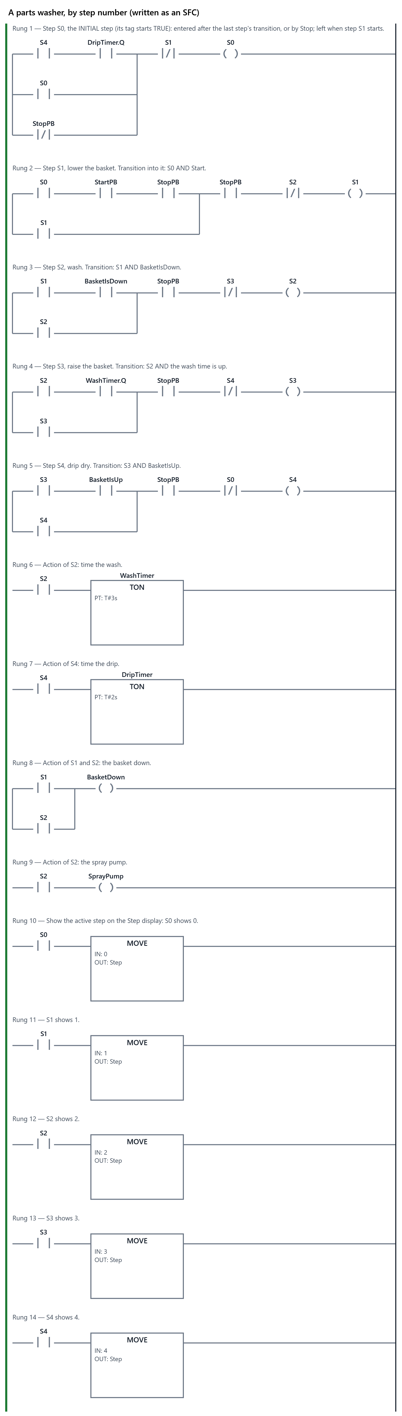
The Example tab runs the parts washer written this way: one BOOL per step, S0 to S4, S0 starting TRUE. (My program cannot give a tag a starting value yet; the Example's program has one.)
Try it
- Open the Example tab. It starts with Written as an SFC chosen in Program, above the machine. Press Start and watch S0 to S4 take turns, and read each rung's comment: which part of the chart is it? Compare it with Works, the same machine with a step number.
- Open the Exercise tab and answer the questions; press Check my answers. These are practice: a wrong answer shows you the right one. This item is complete when you pass its questions.
The questions (on the Exercise tab)
7 questions; the learner needs 80 % to pass and can try again. Practice: a wrong answer shows the right one. The right answers are marked ✓ here only.
Match each one. Match each part of a Sequential Function Chart to what it means.
A box with a name→ A step: active while the machine is in itA box with a double border→ The initial step: active when the PLC startsA bar across the line, with a condition→ A transitionA box beside a step→ An action: what the step does
Why: Steps are boxes, the initial step has a double border, transitions are bars with conditions, and actions sit beside their steps.
Choose one. When does a transition fire?
- ✓ When the step before it is active AND its condition is TRUE
- Whenever its condition is TRUE, whichever step is active
- When the step after it is active AND its condition is TRUE
- Once in every scan, whatever its condition and the steps say
Why: A transition belongs to the step before it. BasketIsDown means nothing in step S3; it moves the chart on only while S1 is active.
Choose one. In the parts washer's chart, S2 (wash) is active and the wash time is up (WashTimer.Q is TRUE). What happens?
- ✓ S2 goes inactive and S3 (raise the basket) goes active
- S3 (raise the basket) goes active, and S2 stays active too
- Nothing yet: S2 stays active until Start is pressed again
- S2 goes inactive and the chart goes back to S0 (idle)
Why: The transition below S2 is WashTimer.Q. It fires: the step before it ends and the step after it starts, in the same moment.
Choose one. An action in step S1 has the qualifier N. When is it on?
- ✓ While S1 is active, and off as soon as S1 ends
- From S1 on, and it stays on until a reset action turns it off
- For one scan only, at the moment S1 becomes active
- Once S1 has been active for a set time, until S1 ends
Why: N (non-stored) is the usual action: on exactly while its step is active, like a coil driven by the step's bit. S stays on, P pulses once, D waits.
Choose one. A chart splits on a double line into two paths: one fills a tank while the other heats an oven. What does that mean?
- ✓ Both paths run at the same time, and the chart goes on only when both are done and meet again at a double line
- Only one path is taken, the first whose transition comes true, and the other is skipped
- Both paths run, one after the other: the left path first, then the right when it is done
- It is a drawing mistake: a chart cannot split, so the tool refuses to run it
Why: A double line is a simultaneous (parallel) branch: every path runs. A single line is a selection: one path is chosen.
Choose one. You write the washer's chart in ladder with one BOOL per step, S0 to S4. How do you make S0 the initial step?
- ✓ Give S0 a starting value of TRUE, so it is active when the PLC starts
- Put S0's rung last, so it is the step left active at the end of the first scan
- Put S0's rung first, so it is the first step the PLC runs when it starts
- Nothing: every BOOL starts TRUE, so S0 is already active when the PLC starts
Why: BOOL tags start FALSE unless they are given a starting value. The program on the Example tab declares S0 with the starting value TRUE. With a step number, step 0 is the initial step, because an INT starts at 0.
Type the answer. In the ladder version of the washer's chart, step S3's rung starts S3 from the step before AND a condition. Type the step before S3 (such as S1).
✓ S2 (case, spaces and underscores do not matter)
Why: S3 (raise the basket) comes after S2 (wash): its rung starts it from S2 AND WashTimer.Q, the transition between them.
Your comments on this item
8.5 Module check
about 25 minutes
- Module check
- Complete when every item it covers is: 8.1, 8.2, 8.3, 8.4. Its questions, on the Exercise tab, are below; it is complete when those items are and the questions are passed. Once it is complete, the learner makes the PDF progress report to hand in (Hand in a report).
The Learn tab
Module check: sequencing and state machines
This check covers the four items of module 8. The stamping station, the batch tank and the gate are complete when their programs pass every test on the Exercise tab; the SFC item is complete when its practice questions are passed.
The check itself is ten questions, on the Exercise tab. Some ask what step or state a machine is in from what you can see. Three are find the fault: a machine runs the working program, but a sensor's wire is broken or a solenoid has failed. Work the machine, watch the rungs and the cylinders, and say what is wrong. A failed solenoid looks different from a broken sensor: in one, the rung turns the output on and nothing moves; in the other, the cylinder arrives and the program never notices. You need 80 % to pass, and you can try again.
When all the items are complete and you have passed the questions, the module is complete and ready to hand in: Hand in a report (the second row of the path) makes the PDF progress report for your instructor, with your score on each exercise and a picture of each program.
The questions (on the Exercise tab)
10 questions; the learner needs 80 % to pass and can try again. A wrong answer says “not quite, look again”; the reason is shown once the answer is right. The right answers are marked ✓ here only.
Choose one. In step logic (one memory bit per step), what ends step 2 of the stamping station?
- ✓ Step 3 starting: a normally closed contact of Step3 in step 2's rung (or Stop)
- Start being let go: a normally open contact of StartPB in step 2's rung (or Stop)
- StampDown turning off: a normally open contact of StampDown in step 2's rung (or Stop)
- A timer: a normally closed contact of a TON's Q, timed to the step, in step 2's rung
Why: Each step is a seal-in that the NEXT step breaks. So exactly one step is on: the moment step 3 starts, step 2 ends.
Find the fault: a machine with a faulty wire, running the working program. This stamping station runs the working program, but something is wrong with its wiring or its cylinders. Turn Part in place to Part in, press Start, and watch the cylinders and the rungs. Which fault does it have?
Machine: A stamping station in four steps; the fault:
ClampIsOut:open- ✓ The clamp's fully-out sensor (ClampIsOut) has a broken wire: it always reads FALSE
- The clamp's solenoid has failed: ClampOut turns on, but the clamp never moves
- The stamp's solenoid has failed: StampDown turns on, but the stamp does not move
- The Part in place switch has a broken wire: PartIn always reads FALSE
Why: The clamp goes fully out, but the station waits in step 1: StampDown never turns on, because ClampIsOut never reads TRUE. A failed stamp solenoid would show StampDown ON on the rungs, with the stamp not moving.
Choose one. The stamping station is working. The clamp is fully out, StampDown is off, and the stamp is on its way back up (StampIsDown and StampIsUp are both FALSE). Which step is on?
- Step 1
- Step 2
- ✓ Step 3
- Step 4
Why: Step 3 (stamp up) starts when the stamp is fully down and lasts until it is fully up. The clamp stays out in step 3; it is released in step 4.
A number. The batch tank runs the working program. The tank is at 50 % and rising, the fill valve is open and the mixer is off. What number does the Step display show?
✓ 1 (within 0)
Why: Step 1 fills: the fill valve is open only in step 1, until the high float.
Find the fault: a machine with a faulty wire, running the working program. This batch tank runs the working program, but one input is faulty. Press Start and watch the tank, the Step display and the rungs. Which fault does it have?
Machine: Fill, mix and drain a batch, by step number; the fault:
HighFloat:open- ✓ The high float has a broken wire: it always reads FALSE, so step 1 never ends and the tank overflows
- The low float has a broken wire: it always reads FALSE, so step 3 ends at once and the tank never drains
- The fill valve has failed: FillValve turns on, but no water comes in and the tank stays empty
- The mixer has failed: the step moves to 2, but the mixer does not turn and the batch is not mixed
Why: The tank passes 80 % and the display stays at 1: the rung that moves to step 2 needs HighFloat, and it never reads TRUE. The tank fills until it overflows, which is why real tanks also have an overflow pipe and a high-high alarm.
Choose one. Why does the batch tank's Start rung need an EQ Step 0 box?
- ✓ Without it, Start pressed in the middle of a batch moves Step back to 1 and fills the tank again
- Without it, Start would move Step to 1 on every scan while held, and the tank would never fill
- Without it, Stop could not move Step back to 0, because MOVE 1 would always run after it
- Without it, the program will not run: a MOVE box must have a compare box in front of it
Why: MOVE 1 runs whenever power reaches it. The EQ box limits Start to step 0, idle.
Find the fault: a machine with a faulty wire, running the working program. This gate runs the working program, but something has failed. Press Open and watch the gate, the State display and the rungs for 5 s. Which fault does it have?
Machine: A gate as a state machine; the fault:
GateClose:failed- ✓ The close solenoid has failed: the PLC turns GateClose on, but the gate does not move
- The fully-closed sensor (GateIsClosed) has a broken wire: the gate closes, but the state stays at 3
- The air pressure is low: AirOK reads FALSE, so the gate stops and the state goes to 9
- The open timer never runs out: the state stays at 2 and the gate stays open
Why: After 3 s open, the state goes to 3 (Closing) and the GateClose rung is ON, but the gate stays fully open. With a broken GateIsClosed wire the gate would close and the state would stay at 3; with low air the state would be 9.
Choose one. The gate stopped half open, and the State display shows 9 (Stopped). Stop is let go and the air pressure is OK. Someone presses Reset. Which state comes next, and why?
- ✓ Closing (3): the gate could be anywhere, so it closes before the machine is idle
- Closed (0): Reset always takes a state machine straight back to idle
- Opening (1): the gate was half open, so it finishes opening first
- Stopped (9): Reset only clears the light; the state waits for Open
Why: Closed (0) assumes the gate is closed. Going there straight from a half-open gate would leave the program believing something untrue, and nothing would close it.
Match each one. Match each idea to its place in a ladder program.
A transition from state 3 to state 1→ EQ State 3, the condition, MOVE 1 to StateA move from any state to Stopped→ The condition, MOVE 9 to State, with no EQ boxAn output on in states 1 and 3→ EQ State 1 and EQ State 3 side by side, then one coilThe SFC initial step→ A step bit that starts TRUE, or state 0
Why: Transitions are EQ, condition, MOVE; a move from any state has no EQ; an output gets one rung; the initial step is active when the PLC starts.
Choose one. In the gate program, the rung that moves to Stopped (9) when Stop is pressed comes after all the other transitions. Why?
- ✓ If another transition happens in the same scan, the stop runs last and wins
- Rungs above the transitions run before the inputs are read, so Stop would be missed
- A rung without an EQ box runs only once it is below every rung that has one
- So that Stop works only once the other transitions have finished moving the gate
Why: The PLC runs rungs top to bottom; the last MOVE into State in a scan is the one that counts. The safety move must have the last word.