
All programs › BMPFast › Sample problems
Routing: untreated catchment into a retention basin
BMPFast sample project: 99 ac with no treatment routed to a 1 ac catchment with retention.
Help: Routing (help page 220) · Download the .bmpt · Link to Solution in BMPFast Version 2
1The problem
The BMPFast sample project no BMP upstream retention: a large catchment with no treatment drains to a small catchment whose retention basin treats both.
| Input | Value | Source |
|---|---|---|
| Project (General Site Information) | ||
| Meteorological zone | Florida Zone 2 | Zone map (help page 815) |
| Mean annual rainfall | 50 in | Mean annual rainfall map (help page 815) |
| Performance standard (analysis type) | Specified Removal Efficiency | BMPFast sample project |
| Specified removal: TN / TP | 75 % / 75 % | BMPFast sample project |
| Catchment 1: downstream (Watershed Characteristics) | ||
| Land use, pre / post | User Defined Values / User Defined Values | BMPFast sample project |
| Area, pre / post | 1 / 1 ac | BMPFast sample project |
| Non-DCIA curve number, pre / post | 70 / 70 | BMPFast sample project |
| DCIA, pre / post | 24.33 / 24.33 % | BMPFast sample project |
| EMC TN, pre / post | 0.811 / 0.811 mg/L | BMPFast land use table (AH Vol I Table 9.2) |
| EMC TP, pre / post | 0.811 / 0.811 mg/L | BMPFast land use table (AH Vol I Table 9.2) |
| BMP used in routing | Retention: retention volume 4.167 ac-ft | BMPFast sample project |
| Routes to | the Outlet | BMPFast sample project |
| Catchment 2: upstream (Watershed Characteristics) | ||
| Land use, pre / post | User Defined Values / User Defined Values | BMPFast sample project |
| Area, pre / post | 99 / 99 ac | BMPFast sample project |
| Non-DCIA curve number, pre / post | 70 / 70 | BMPFast sample project |
| DCIA, pre / post | 24.33 / 24.33 % | BMPFast sample project |
| EMC TN, pre / post | 0.811 / 0.811 mg/L | BMPFast land use table (AH Vol I Table 9.2) |
| EMC TP, pre / post | 0.811 / 0.811 mg/L | BMPFast land use table (AH Vol I Table 9.2) |
| BMP used in routing | No Treatment (no BMP) | BMPFast sample project |
| Routes to | Catchment 1 | BMPFast sample project |
Find: the loads leaving the site when the catchments are routed through each other, and how BMPFast treats the chain.
2Steps in BMPFast
Press Open Project and open
routing-no-treatment-to-retention.bmpt(the file under Files; it is the BMPFast sample project No BMP Upstream then retention.bmpt). General Site Information (the main window; its title bar reads General Site Information and your license key) shows Florida Zone 2, 50.0 in of rainfall and the performance standard Specified Removal Efficiency.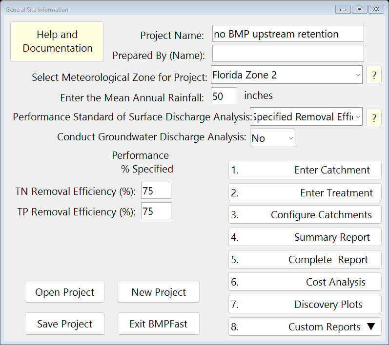
General Site Information (the main window). Press 1. Enter Catchment and click Catchment 1 in the menu bar at the top of the Watershed Characteristics Worksheet. It holds: name downstream; land uses User Defined Values (pre) and User Defined Values (post); areas 1 and 1 ac; non-DCIA CN 70 and 70; DCIA 24.33 and 24.33 %. Press Back.
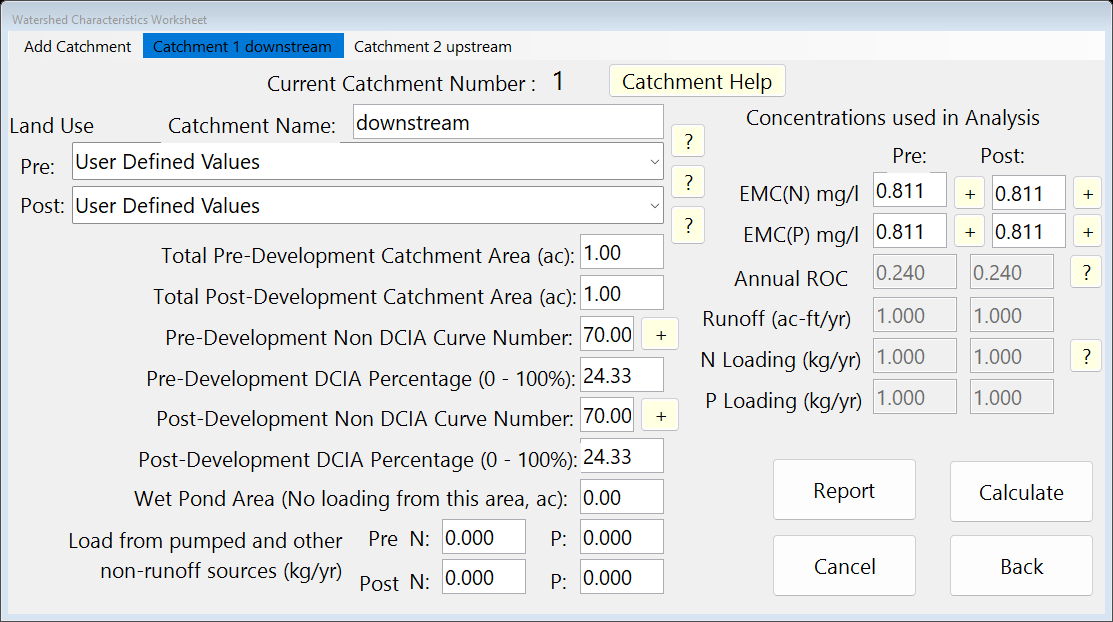
Watershed Characteristics, Catchment 1. On the Watershed Characteristics Worksheet click Catchment 2 in the menu bar: name upstream; land uses User Defined Values (pre) and User Defined Values (post); areas 99 and 99 ac; non-DCIA CN 70 and 70; DCIA 24.33 and 24.33 %.
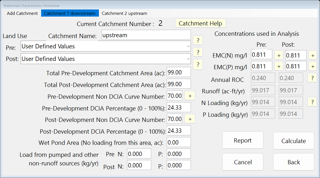
Watershed Characteristics, Catchment 2. Press 2. Enter Treatment, click Catchment 1 in the menu bar to make it current, and press Retention Basin to see its BMP: retention volume 4.167 ac-ft. Press Calculate, then Back.
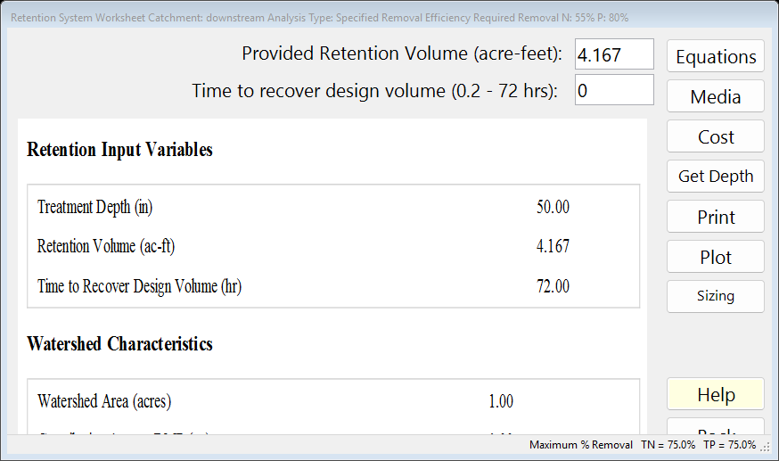
The BMP worksheet after Calculate: the report on the left. On the main window press 3. Configure Catchments. in the row of Catchment 1 press Edit (the Routing Catchment From: 1 window opens). In Select BMP to use in routing choose Retention; in Select Catchment to Route to choose the Outlet. Press Back.
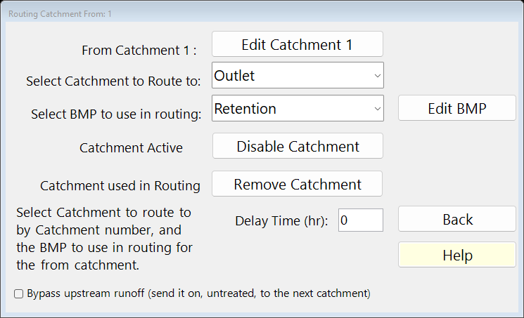
Routing for Catchment 1. Back on Select Catchment Configuration, in the row of Catchment 2 press Edit (the Routing Catchment From: 2 window opens). In Select BMP to use in routing choose No Treatment; in Select Catchment to Route to choose Catchment 1. Press Back (Back again closes Select Catchment Configuration).
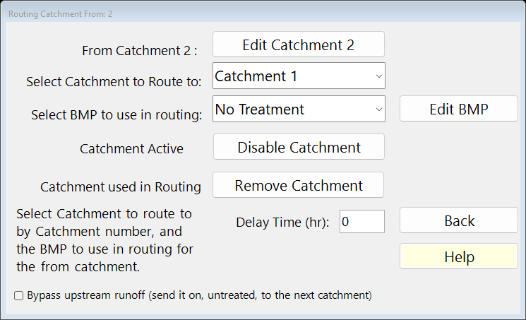
Routing for Catchment 2. Select Catchment Configuration now lists every catchment: From, To (0 is the Outlet), area and the BMP used.
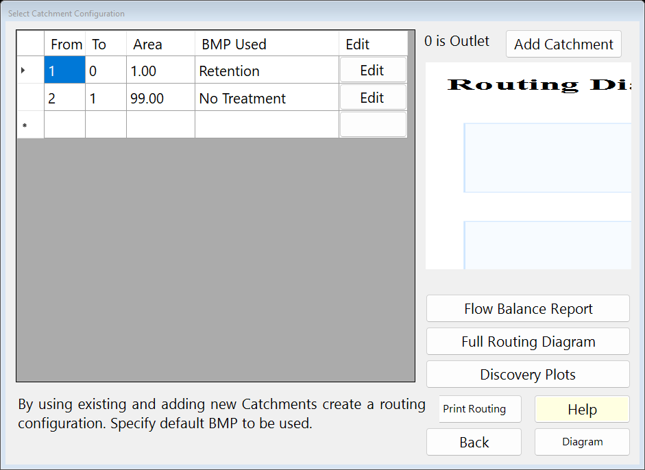
Select Catchment Configuration (3. Configure Catchments). Press Diagram to see the network.
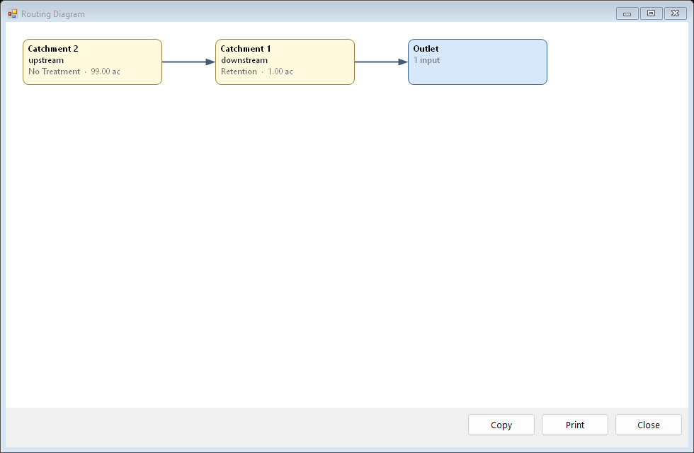
The routing Diagram. Press Full Routing Diagram for the routing report: each strand and the method used. Press Back.
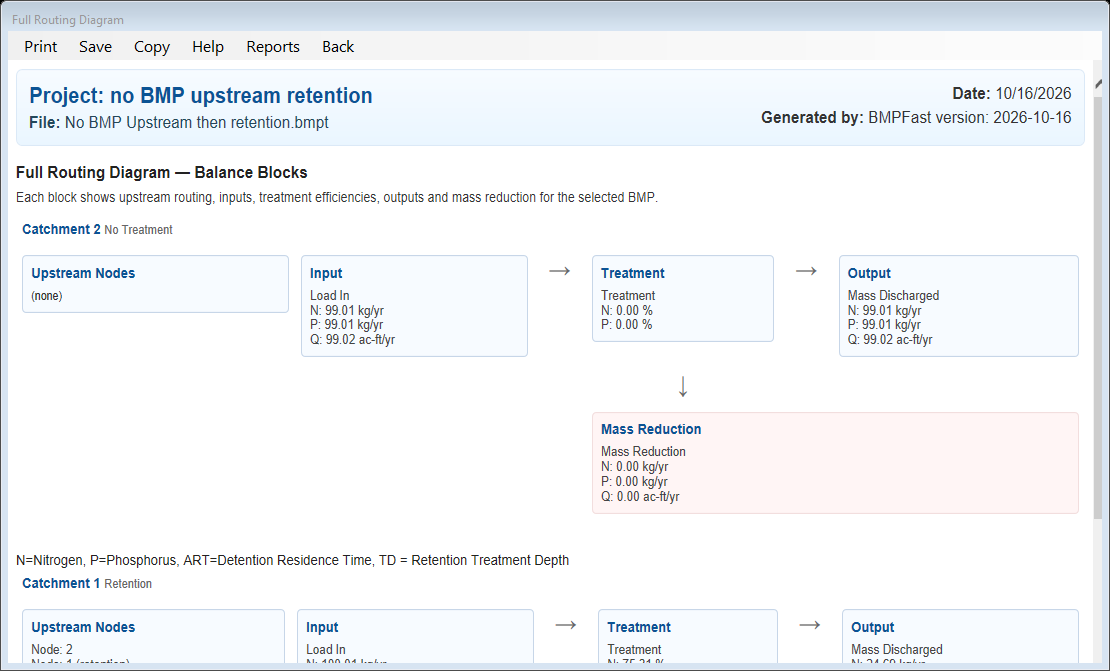
The Full Routing Diagram report. Press 4. Summary Report. The Report Viewer shows the loads, the removal and whether the performance standard is met. Press Save Project to keep your copy; compare it with the .bmpt under Files.
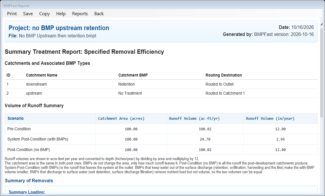
The Summary Report (4. Summary Report) in the Report Viewer.
3Results
| Catchment | Runoff (ac-ft/yr) | TN load (kg/yr) | TP load (kg/yr) | BMP → routes to |
|---|---|---|---|---|
| 1. downstream | 1.000 | 1.000 | 1.000 | Retention → the Outlet |
| 2. upstream | 99.017 | 99.014 | 99.014 | No Treatment → Catchment 1 |
| Result | Value |
|---|---|
| Site (all catchments, at the outlet) | |
| TN load: catchments → outlet | 100.014 → 24.695 kg/yr |
| TP load: catchments → outlet | 100.014 → 24.695 kg/yr |
| Provided removal TN / TP | 75.3 % / 75.3 % |
| Required removal TN / TP (Maximum % Removal) | 75.0 % (met) / 75.0 % (met) |
Strands found by BMPFast (a strand is a run of catchments in series that BMPFast may calculate as one system):
- Catchments 2 → 1 form one strand, “Upstream No Treatment routed to Retention”: BMPFast calculates them as one system (TN in 100.014 kg/yr, removal 75.31 %, out 24.695 kg/yr).
The Full Routing Diagram report
Open this report on its own page.
The Summary Report
4Check
Loads.
Each catchment’s load is EMC × runoff × 1.233 (Equation 9-2). Together:
| TN 1.000 + 99.014 | = 100.014 kg/yr (program 100.014) |
TP 100.014 kg/yr (program 100.014).
No treatment upstream of retention (the strand rule).
BMPFast finds the strand “Upstream No Treatment routed to Retention”. The basin of Catchment 1 receives the runoff of both catchments, so the strand is one retention system for the whole drainage area: its 4.167 ac-ft over all 100 ac is a treatment depth of 4.167 × 12 / 100 = 0.500 in, and the retention tables at that depth give the system removal, 75.31 %.
| TN out | = 100.014 × (1 − 75.31 / 100) |
| = 24.695 kg/yr (program 24.695). |
This sample project is built so the total load is 100 kg/yr (both EMCs 0.811 mg/L), so the outlet load in kg/yr is the percentage not removed. See Strand Based Routing for No Treatment to Retention.
5Files
- routing-no-treatment-to-retention.bmpt: the project, saved by BMPFast. Save it (your browser puts it in Downloads). In BMPFast press Open Project, then Open Project again in the Open BMPFast Project dialog (below its Recent Projects list), and choose the file.
- Full Routing Diagram report (as BMPFast shows it)
- Summary Report (as BMPFast shows it)
6Help and methodology
- Routing (help page 220)
- Catchment Configurations (help page 196)
- Strand Based Routing for Wet Detention in Series (help page 4823)
- Strand Based Routing for Retention in Series (help page 4824)
- Strand Based Routing for No Treatment to Detention (help page 4833)
- Strand Based Routing for No Treatment to Retention (help page 4834)
- All sample problems
Calculated with BMPFast 1.1.9 (build 6.0.0, 2026-10-16). Older versions may not have the Equations button or may give slightly different results; download the latest at bmpfast.com. Screen captures are for demonstration only.