Pipe flow
Normal depth, velocity, full-flow capacity, critical depth and Froude number of a circular pipe, box culvert or open channel in uniform flow, from its shape, slope, roughness and flow, with a storm-sewer design check.
What it is for
Pipe flow answers the everyday storm-sewer question: a pipe or channel laid at a known slope must carry a known flow, so how deep does the water run, how fast is it moving, and does the section have the capacity? It assumes uniform flow, where the water surface runs parallel to the invert and friction exactly balances the pull of gravity along the slope. The depth that satisfies that balance is the normal depth.
You choose the shape (circular pipe, box culvert, rectangular channel or trapezoidal channel) and enter only the dimensions that shape needs: a diameter, or a bottom width, rise and side slope. Then you enter the slope as a fraction, the flow, and the roughness for the friction relation you choose: Manning's n, a Darcy–Weisbach friction factor f, or a Hazen–Williams C. You can also work the other way round: leave the flow blank, enter a depth, and SMADA finds the flow the section carries at that depth.
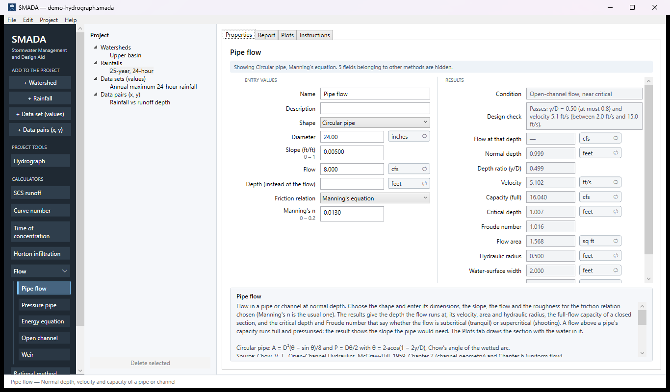
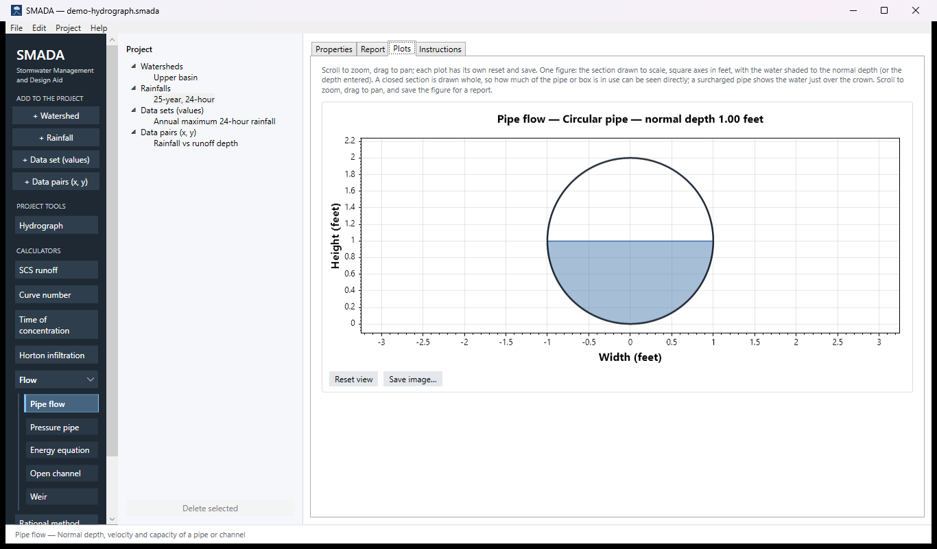
You get back the velocity, the full-flow capacity of a closed section, the critical depth and Froude number that say whether the flow is subcritical or supercritical, the normal depth and depth ratio y/D, the flow area, hydraulic radius and water-surface width, and a one-line condition. For a pipe or box culvert a design check says whether it meets the usual storm-sewer limits (no deeper than 0.8 of its height, 2 to 15 ft/s) and what to change if not, so you can size a pipe by trying diameters until it passes. When the flow is more than a closed section can carry, SMADA reports that it runs full under pressure and gives the slope it would need to run full. The Plots tab draws the section to scale with the water in it.
The flow usually comes from the Rational method or the peak of a Hydrograph. If the pipe runs full and surcharged, carry on with the Pressure pipe calculator; for a natural channel with a surveyed cross-section, or to judge a channel lining by its shear stress, use Open channel.
The Pipe flow tabs
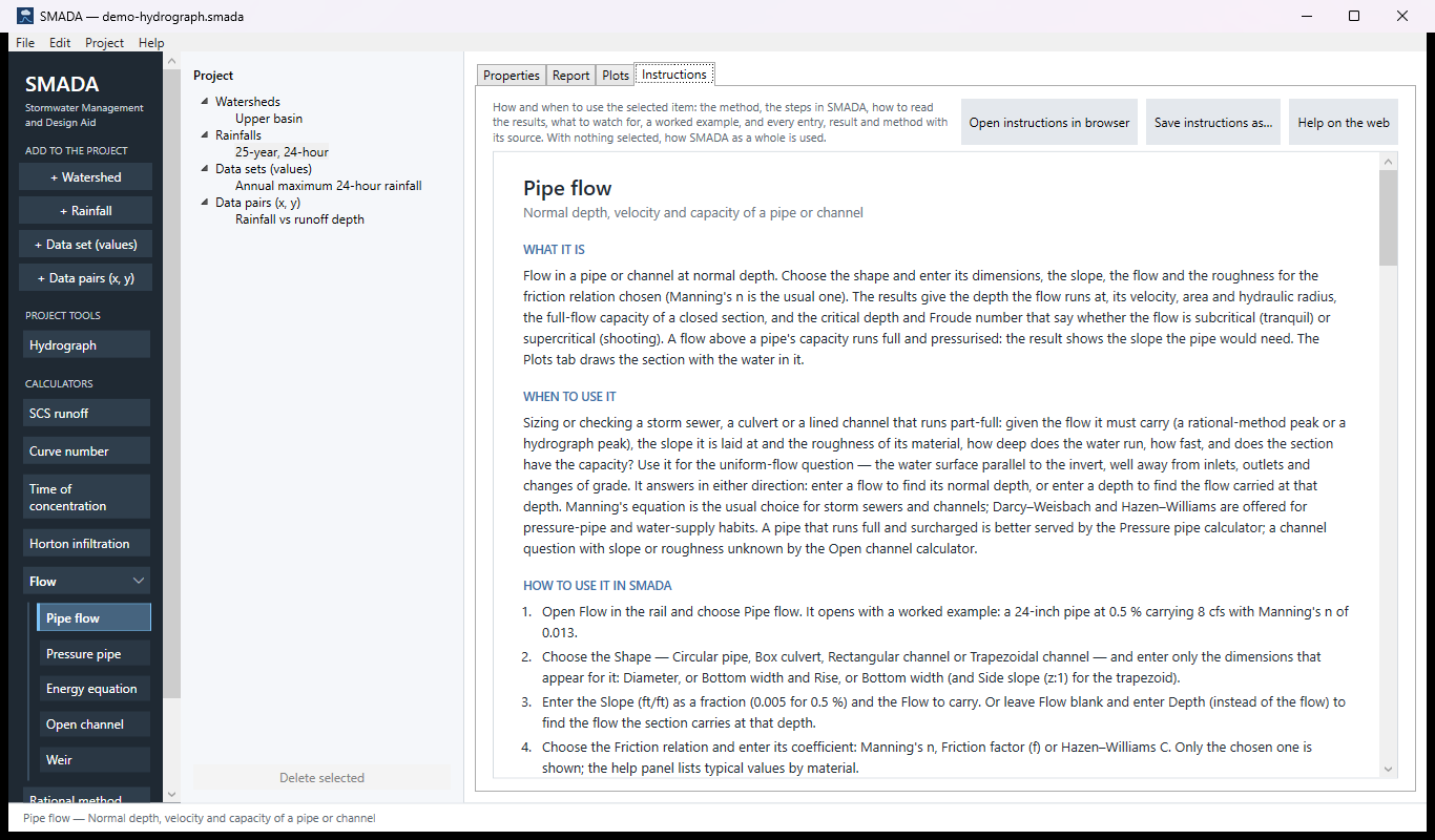
Every item in SMADA has the same four tabs. These are captured from the program with the example values it opens with; select a picture to see it full size.
Properties tab — where you enter values and read the results
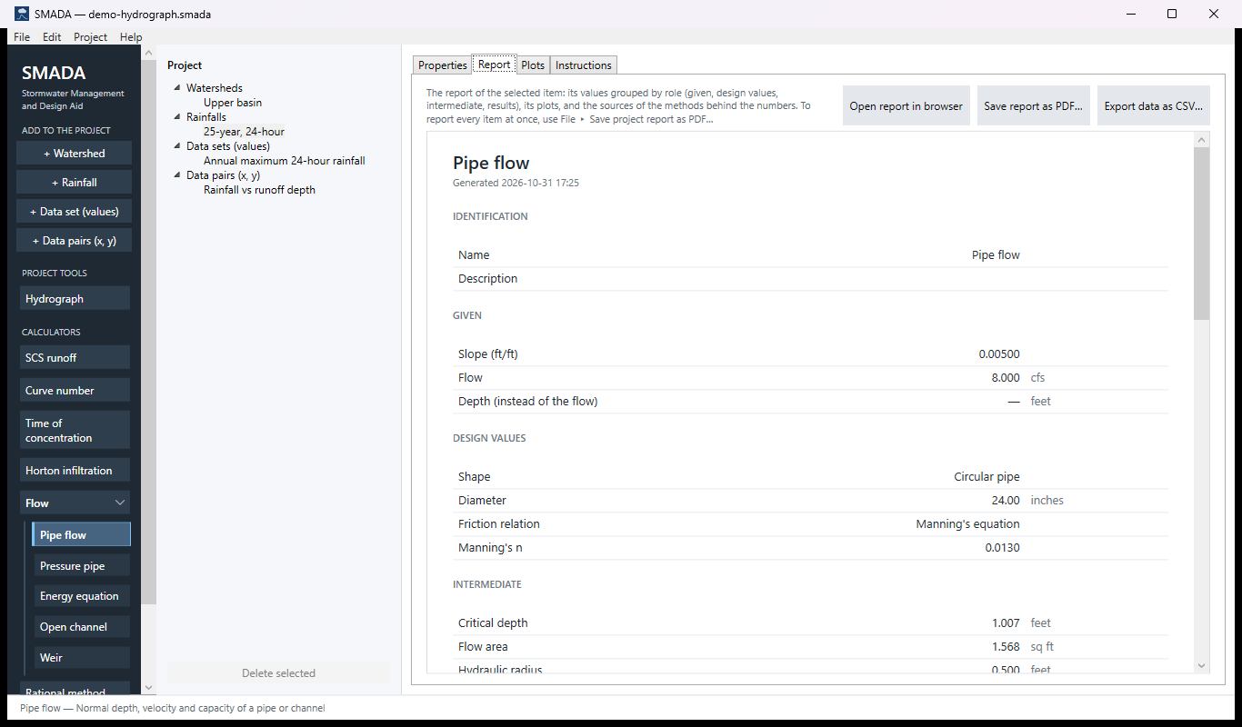
Report tab — the same values as a report, ready for HTML, PDF or CSV
Plots tab — what it draws
Instructions tab — the manual page in the program
How it calculates
Every calculation is in US customary units: lengths in feet, flow in cfs, velocity in ft/s, flow area in sq ft, slope in ft/ft. The pipe diameter is stored in inches and divided by 12; it has its own Pipe size unit button (inches or millimetres), so changing it leaves rainfall depths and other lengths alone. Each result has its own unit button, and every message is written in the units on display. Gravity is g = 32.174 ft/s². The shape supplies three functions of depth — flow area, wetted perimeter and top width — and the friction relation turns them into a velocity. Everything else is built from those pieces.
1. The section's geometry
Each shape gives the area A, wetted perimeter P and top width T at a depth y. A closed section (circular pipe, box culvert) has a full depth, the diameter D or the rise h; an open channel has none.
Circular pipe. The wetted arc subtends the central angle θ (Chow's angle), from 0 when empty to 2π when full:
θ = 2 acos(1 − 2y / D)
A = (D2 / 8) (θ − sin θ)
P = D θ / 2
T = D sin(θ / 2), and T = 0 when y ≥ D
Box culvert (closed rectangle, Bottom width b, Rise h) and rectangular channel (open, bottom width b):
A = b y
P = b + 2y, plus the top b when a box runs full (P = 2b + 2h)
T = b, and T = 0 when a box runs full
Trapezoidal channel (bottom width b, Side slope (z:1) z horizontal to 1 vertical):
A = (b + z y) y
P = b + 2y √(1 + z2)
T = b + 2z y
In every shape the hydraulic radius is
R = A / P
- y
- depth of flow, ft
- D
- pipe diameter, ft
- b
- bottom width: inside width of a box or rectangular channel, or bottom width of a trapezoid, ft
- h
- rise (inside height) of a box culvert, ft
- z
- side slope of a trapezoid, horizontal per unit vertical
- θ
- central angle of the wetted arc, radians
- A
- flow area, sq ft
- P
- wetted perimeter, ft
- T
- water-surface (top) width, ft
- R
- hydraulic radius, ft
2. Velocity from the friction relation
You choose one of three relations under Friction relation. Each gives the mean velocity from the hydraulic radius and the slope; only the chosen relation's coefficient is shown on the form.
Manning's equation (the default):
V = (1.49 / n) R2/3 S1/2
Darcy–Weisbach, written for any section through the hydraulic radius (for a full pipe R = D/4, which gives the familiar hf/L = f V2 / (2g D)):
V = √(8 g R S / f)
Hazen–Williams, for water:
V = 1.318 C R0.63 S0.54
The discharge at a depth is the velocity times the area:
Q = V A
- V
- mean velocity, ft/s
- n
- Manning roughness coefficient
- f
- Darcy–Weisbach friction factor (from the Moody diagram; SMADA does not compute it)
- C
- Hazen–Williams coefficient
- S
- slope of the invert, which in uniform flow is also the friction slope, ft/ft
- g
- 32.174 ft/s²
- Q
- discharge, cfs
Manning's constant is 1.49, as in the old HYDRLICS program and Chow's examples (1.486 is the exact conversion; the difference is 0.27 % in flow). Hazen–Williams uses the constant 1.318, not HYDRLICS's 1.32. The friction factor f is used as you enter it; it is not adjusted for the Reynolds number.
3. Full-flow capacity of a closed section
For a circular pipe or a box culvert SMADA evaluates step 2 with the section exactly full and reports it as Capacity (full) and Full-flow velocity:
Qfull = V(Rfull) Afull
Vfull = Qfull / Afull
For a circular pipe with Manning's equation this is the familiar Qfull = (0.463 / n) D8/3 S1/2, since Rfull = D/4. For a box the full wetted perimeter includes the top. An open channel has no capacity, and both results are left blank.
4. Normal depth
Normal depth is the depth at which Q(y) from step 2 equals the flow you entered. SMADA finds it by bisection, not by a closed form:
- Closed section, flow at or above capacity. If Q ≥ Qfull, the normal depth is set to the full depth (D or h) and the section is treated as running full (step 6).
- Closed section, flow below capacity. A closed section's discharge rises to a peak just below the crown (about 1.076 Qfull at 0.938 D in a circle, where the wetted perimeter starts growing faster than the area) and then falls back to Qfull. SMADA finds that peak by evaluating Q at every 1 % of the full depth from 0.80 to 1.00 and keeping the largest. It then bisects on [0, peak depth], so a flow below capacity always gets the depth on the rising limb of the curve.
- Open channel. The upper bound starts at 1 ft and doubles until Q(y) reaches the flow (or the bound passes 106 ft); then SMADA bisects on [0, bound].
Each bisection runs a fixed 100 halvings of the interval, which settles the depth far below any precision that is reported. This replaces the stepping search on θ in the old HYDRLICS program. Water close to the crown is unstable and seals the pipe, so SMADA never reports a flow above Qfull as part-full, even though Manning's formula alone would carry a few per cent more near 0.94 D: the just-full value is the design figure.
Entering a depth instead of the flow. If you leave Flow blank and enter Depth (instead of the flow), the depth must be greater than zero and, in a closed section, no more than the diameter or rise. SMADA computes the flow at that depth from step 2 and reports it as Flow at that depth; that depth is then used in place of the normal depth for the remaining results. In a closed section, a depth so near the crown that the open-channel formula would give more than Qfull is taken as running full: the flow found is the capacity, and the condition quotes what the open-channel formula alone would have given. In a circle that is any depth above about 0.82 D, where the discharge curve comes back down through Qfull. So the two directions, flow to depth and depth to flow, always agree.
The Depth ratio (y/D) is y / D for a pipe or y / h for a box; it is blank for an open channel.
5. Critical depth and the Froude number
Critical depth is the depth at which, for this flow, the Froude number is one. SMADA finds the root of
1 − Q2 T / (g A3) = 0
by bisection (100 halvings). For a closed section the search runs from 0 to 0.999 of the full depth; if the residual is still negative there, the flow would be supercritical even at the crown and the critical depth is left blank. For an open channel the upper bound starts at 1 ft and doubles until the residual turns positive.
The Froude number is evaluated at the normal depth, with the hydraulic depth A/T:
F = (Q / A) / √(g A / T)
- F
- Froude number, dimensionless
- A/T
- hydraulic depth, ft
For part-full flow the Condition line reads "Open-channel flow, subcritical" for F < 0.95, "supercritical" for F > 1.05, and "near critical" in between. Normal depth above critical depth means subcritical flow; below it, supercritical.
6. Part-full and full results
Part-full (normal depth below the full depth, or any open channel): the velocity is computed from the friction relation at the normal-depth hydraulic radius and the slope you entered (step 2), and A, R, T and F are reported at that depth as Flow area, Hydraulic radius, Water-surface width and Froude number.
Full (a closed section with the flow at or above capacity, or a depth taken as full): the depth ratio is 1, the water-surface width 0, R is the full-section value, the Froude number is reported as 0, and the velocity is simply
V = Q / Afull
SMADA then reports Slope to run full (ft/ft) (in the report, "Slope needed to run full"): the friction slope the full section needs to pass that flow, from the friction relation inverted for S. It is steeper than the slope entered when the pipe surcharges, and equal to it when the pipe runs just full. It is blank for part-full flow and for an open channel.
Manning: S = (V n / (1.49 R2/3))2
Darcy–Weisbach: S = f V2 / (8 g R)
Hazen–Williams: S = (V / (1.318 C R0.63))1/0.54
When the flow is above capacity the condition says it runs full under pressure and quotes the capacity; when it equals the capacity, or a depth was taken as full, it reads "Runs just full".
7. Design check
For a pipe or box culvert SMADA compares the result with common storm-sewer criteria at the design flow, and Design check reads "Passes" with the values, or "Does not pass" with what to change:
- A flow above the capacity fails: try the next larger size or a steeper slope.
- Otherwise a depth ratio y/D above 0.8 fails: try the next larger size.
- A velocity under 2 ft/s fails, since sediment may settle: a steeper slope or a smaller size helps.
- A velocity over 15 ft/s fails, since the pipe may scour: a flatter slope helps (drop manholes or drop structures take up the fall); a larger size at the same slope barely slows it.
The velocity limits follow ASCE Manual of Practice 77 / WEF FD-20 and FHWA HEC-22; the 0.8 depth ratio is a common agency criterion rather than a national standard. Your local criteria govern where they differ (many agencies ask for 3 ft/s). An open channel is not checked: the line says so and points to the shear stress in the Open channel calculator, which is how a lining is judged.
Checks SMADA applies
- A diameter, width or rise must be greater than zero; a trapezoid needs a bottom width and a side slope, at least one of them greater than zero.
- The slope and the roughness coefficient must be greater than zero, and either a flow or a depth must be entered. If both are entered the flow is used and the depth ignored.
- A depth entered instead of the flow must be greater than zero and, in a closed section, no more than the diameter or rise; the message quotes that limit in the units on display.
Checking the example by hand
A 24-inch pipe (D = 2 ft), S = 0.005, n = 0.013, Q = 8 cfs. Full: A = π(2)2/4 = 3.142 sq ft, R = 0.5 ft, V = (1.49 / 0.013)(0.5)2/3(0.005)1/2 = 5.106 ft/s, so Qfull = 16.040 cfs. Half full, θ = π, A = 1.571 sq ft and P = π ft, so R is again 0.5 ft, the velocity is the same and Q = 8.020 cfs — a little over 8, so 8 cfs runs just under half depth. The bisection gives a normal depth of 0.999 ft (y/D 0.499), with A = 1.568 sq ft and R = 0.4995 ft, so V = (1.49 / 0.013)(0.4995)2/3(0.005)1/2 = 5.102 ft/s. At that depth T = 2.000 ft, so F = (8 / 1.568) / √(32.174 × 1.568 / 2.000) = 1.016, just inside the near-critical band; the critical depth, where F = 1, is slightly higher at 1.007 ft. The design check passes: y/D 0.50 is under 0.8, and 5.1 ft/s lies between 2 and 15 ft/s.
Sources
- Chow, V. T., Open-Channel Hydraulics, McGraw-Hill, 1959, Chapter 2 (channel geometry) and Chapter 6 (uniform flow).
- Manning, R., "On the flow of water in open channels and pipes", Trans. Inst. Civil Engineers of Ireland 20, 1891; Chow, V. T., Open-Channel Hydraulics, 1959, Chapter 5.
- Moody, L. F., "Friction factors for pipe flow", Trans. ASME 66, 1944; Chow, V. T., Open-Channel Hydraulics, 1959, Chapter 1.
- Williams, G. S. and Hazen, A., Hydraulic Tables, 3rd ed., Wiley, 1920.
- ASCE and WEF, Design and Construction of Urban Stormwater Management Systems, ASCE Manual of Practice No. 77 / WEF Manual of Practice FD-20, 1992 (minimum self-cleansing velocity of 2 to 3 ft/s; maximum velocity to limit scour); FHWA, Urban Drainage Design Manual, HEC-22, 3rd ed., 2009, storm drain design criteria. The source of the design check.
All SMADA calculators · Get SMADA free for Windows from the Microsoft Store