
The configure option is where the routing actually happens. This screen (window title Select Catchment Configuration, opened with 3. Configure Catchments on the General Site Information screen) lists every catchment, shows where each one sends its water and which BMP treats it, and lets you route them to one another and to the outlet. Use it after you have entered your catchments and chosen their BMPs, whenever the site has more than one catchment or a treatment train.
By default every catchment flows to the outlet (0). To build a treatment train, send an upstream catchment to the catchment downstream of it: its outflow, after its own BMP, becomes an input to that catchment’s BMP. See Routing for how the routed loads are calculated.
Spreadsheet Blocks
The grid has one row per catchment. Disabled catchments are shown in grey. None of the cells can be typed in; use Edit to change a row.
| Column | Units | Meaning |
|---|---|---|
| From | – | This is the catchment number that will be routed. |
| To | – | Where its water goes: another catchment (and that catchment’s BMP) or the outlet. “0 is Outlet”. |
| Area | ac | The catchment’s total post-development area. |
| BMP Used | – | The BMP that treats this catchment in routing (its default BMP). Any of the treatments defined for the catchment can be chosen on the Routing screen. |
| Edit | button | Opens the Routing screen for this (upstream) catchment, where you choose To, the BMP used, and enable, disable or remove the catchment. The grid and diagram refresh when you return. |
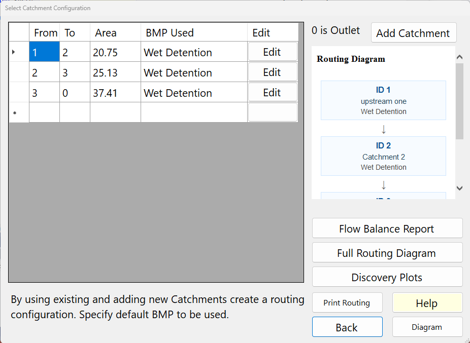
Routing Diagram panel
The panel at the top right draws the routing as columns of blocks, one column per chain of catchments, each block showing the catchment ID, name and BMP, with arrows down to Outlet (0). It says “No routing defined.” or “No catchments defined.” when there is nothing to draw. If a catchment falls in more than one strand, a red Caution: Routing Limitation box lists it, because its load would be counted more than once if strands were added together.
Surface Discharge Filters in series
When a catchment whose BMP is a Surface Discharge Filter (Filtration in the BMP Used column) drains to another catchment whose BMP is also a Surface Discharge Filter, and both filters are defined, a choice appears under the Routing Diagram panel: Surface Discharge Filters (Filtration) in series. It does not appear for any other routing.
- Handbook equation (each filter alone), the default: each filter is calculated on its own and the results are combined as a treatment train (Applicant’s Handbook Vol. I, Equation 9-5).
- Equivalent Treatment Depth (one system): the filters act as one retention. Each filter’s removal is turned into the Treatment Depth that gives it on the retention curves; the depths are added, and the removal is the curves at the sum. It is used for a run of catchments one after another with no other water joining them, whose BMPs are all Surface Discharge Filters.
The project is recalculated when you choose, and the line under the list says which catchments the Equivalent Treatment Depth was used for, and why it was not used for any other filter-to-filter link (for example, two catchments draining into the same one). The Flow Balance Report shows each system. The choice is saved with the project. The Equivalent Treatment Depth is not in the Handbook: say in your submittal which method you used. Both methods are worked through with numbers in Comparison of Methods for Calculating Filters in Series (the link under the list opens it).
Buttons
| Button | What it does |
|---|---|
| Add Catchment | Opens the Catchment Editor (the Watershed Characteristics Worksheet), at Catchment 1. Add the new catchment there with its Add Catchment menu, then return; the grid refreshes. A new catchment routes to the outlet (0) until you change it. Its tooltip says the same. |
| Flow Balance Report | Recalculates and shows a report for each strand of the routing: the Retention in Series report for an all-retention strand, the Detention in Series report for an all-wet-detention strand, and a flow balance (flows and loads into and out of each catchment) for every other strand. |
| Full Routing Diagram | Recalculates and opens the Full Routing Report: a full balance and removal for all catchments in the configuration, drawn strand by strand. |
| Discovery Plots | Opens Discovery Plots for the whole system: pick an independent variable to vary and the results to plot. |
| Print Routing | Opens the Routing Diagram panel’s drawing in the report viewer, where it can be printed. |
| Diagram | Opens the Routing Diagram window (below). |
| Help | Opens this page. |
| Back | Closes the screen. Routing changes are already stored in the project (save the project file from the main screen). |
Routing Diagram window (Diagram button)
A read-only drawing of the routing tree. The outlet is on the right and water flows left to right. The outlet block shows how many inputs it has; each catchment block shows “Catchment n”, its name (or “(unnamed)”), and its BMP and post-development area. Catchments that flow straight to the outlet are in the first column to its left, those that flow into them in the next column, and so on; the inputs to a block are stacked beside it in catchment order, so arrows never cross. The window can be resized and scrolled.
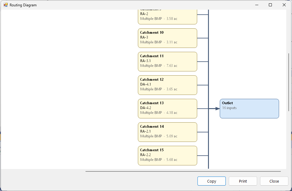
- Right-click a catchment block for its reports: Catchment n Report (the catchment’s inputs and loads); for its default BMP, … (default) — Standalone Report (the BMP on its own catchment only, as on its treatment screen) and … (default) — Routing Report (the catchment as a node in the routing: volumes from the catchment and from upstream, N and P loads in, removal and loads out); and a Standalone Report for every other BMP defined on the catchment. The outlet has no menu.
- Dashed arrow: a catchment routed to a disabled or missing catchment (or to itself) is drawn going to the outlet with a dashed arrow, because that is where the calculation sends it; the routing table at the start of the Complete Report warns about it too. The note at the bottom names it, e.g. “Catchment 1 (to disabled 2)”. Point at the note to read it in full, with what to do if it is not intended: enable the catchment it routes to (Routing screen) or change where it routes.
- Not shown: a disabled catchment, or one in a routing loop, is left off the diagram and named in the same line.
- Copy puts the drawing on the clipboard as a picture. Print prints it, scaled to fit one page. Close (or Esc) closes the window.
Adding Catchments to Routing
The Add Catchment button will allow you to add a Catchment to a routing. You can define catchments that you do not use in routing (disable them on the Routing screen). This allows you to easily compare options by changing the catchments used in a routing.
Special Cases
BMPFast handles a number of special calculation cases. A run of catchments in series, where none of them receives water from more than one catchment, is a strand. A strand is calculated as a single system when it is:
- Retention in Series – every BMP in the strand is a retention-type BMP;
- Detention in Series – every BMP is a wet detention;
- No Treatment to Detention or No Treatment to Retention – untreated catchments flowing into a wet detention or a retention BMP.
Source reference
BMPFast method (ComplexRouting.CalculateWithStrands and StrandCalculations; ponds in a chain calculated with all the runoff reaching each pond, Ron, 2026-10-15): catchments are worked from upstream to the outlet with loads in kg/yr; strands of retention BMPs, of wet ponds, and of untreated catchments into a pond or retention BMP are calculated as single systems, and every other node on its own.
FDEP and the water management districts (2010). Stormwater Quality Applicant’s Handbook: Design Requirements for Stormwater Treatment Systems in Florida, March 2010 draft (not adopted), Section 22.3 Dry Retention In Series, Table 22.3-2, notes 2 and 3 (the draft, not adopted: PDF, 16 MB): in its worked example the downstream basin’s efficiency is read from the dry retention tables at the sum of the two basins’ retention depths (2 in = 1.00 + 1.00 in; 1.89 in = 1.00 + 0.89 in), and the downstream basin is credited with the difference from the upstream basin’s efficiency; BMPFast’s Equivalent Treatment Depth adds the depths in the same way.
Any other strand is calculated catchment by catchment. See Routing for details.
Applicant’s Handbook reference
Section 9.5.1 Treatment Train Nutrient Reduction (Equation 9-5): BMPs in series combine by Equation 9-5 when they act independently, and the designer “should consider the use of another methodology” where an upstream BMP changes how a downstream one performs; BMPFast routes other strands node by node (Equation 9-5 in mass form) and calculates these special cases as one system.
Reports
- Flow Balance Report – one report per strand (Retention in Series, Detention in Series, or flow balance).
- Full Routing Diagram – the Full Routing Report for all catchments.
- Print Routing – the routing block diagram for printing.
- The node-by-node routing table (Complex Routing Summary) is the first section of the Complete Report (button 5 on the main screen), together with any routing warnings.
Networks BMPFast can route
Any arrangement of catchments can be routed: catchments in series, several series routing to the outlet, a series routing into another series, and two or more series routing into a single catchment (a junction). BMPFast works through the network from the most upstream catchments to the outlet; at a junction it adds up the flow and loads from every catchment routed into it before applying that catchment’s BMP. See Routing.
These specific scenarios are allowed in the program, and plans are underway to test the different possible routing scenarios for accuracy.
Sample problems
Worked problems solved in BMPFast, each with every input, the steps with screen captures, the program’s results, a hand check and the project file to download. Captures are for demonstration only. All of them: BMPFast sample problems.