
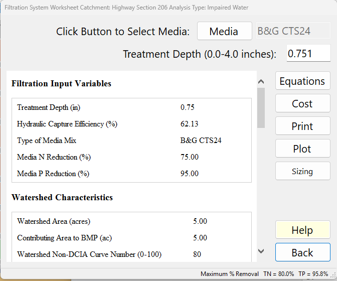
The Filtration System Worksheet is where you enter a Surface Discharge Filter: a bed of filter media (usually a Biosorption Activated Media, BAM) that treats runoff and discharges the treated water to surface water, often through an underdrain. Open it from Treatment Options with the Surface Discharge Filter button. You choose the media and the treatment depth the filter can process; BMPFast calculates the share of the annual runoff that passes through the filter and the nitrogen and phosphorus it removes. The Sizing button opens Surface Discharge Filter Sizing, which finds the minimum filter surface area for a filter fed by an upstream pond (see the Sizing section below).
The media themselves — what each built-in mix removes, its treatment rate, how to add your own mix — are described on the Media Mix page.
Description
Biofilters or biofiltration systems are a suite of BMPs that use engineered media, such as Biosorption Activated Media (BAM), to enhance nutrient removal when native soils cannot provide adequate pollutant removal. Another use is where the native soils do not have an adequate infiltration rate.
Retention basins and detention ponds may use filters on the discharge from the ponds to further remove nutrients, usually the nitrate form of Nitrogen and Phosphorus (Chang, N., Wen, D., Valencia, A., Colona, W., and Wanielista, M. (2019). Comparison of Biological Nutrient Removal via Two Biosorption Activated Media between Laboratory-scale and Field-scale Linear Ditch for Stormwater and Groundwater Co-Treatment. Water, Air and Soil Pollution Journal).
The annual water quality effectiveness is based on the volume that passes through the filter. Not all runoff water (particularly from high rainfall events) will pass through the filter; therefore, the annual removal is less than the maximum filter removal effectiveness.
The USEPA (United States Environmental Protection Agency (2023). Green Infrastructure, April 24. https://www.epa.gov/green-Infrastructure/what-green-infrastruture) defines on-site filters as Green Stormwater Infrastructure devices (GSIs). They may include underdrains for surface discharge and are classified as detention systems; however, they are frequently designed to function as retention systems.
In BMPFast a Surface Discharge Filter is not a retention BMP: its treated water is a surface discharge. Before a media is used within the State of Florida, acceptance must be granted by the review or regulatory agency; confirm the treatment rate and removal with the agency before finalizing annual removal documentation.
Inputs
| Input | Units | What it means / how it is used |
|---|---|---|
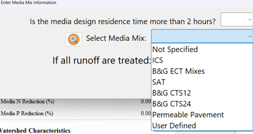
| Click Button to Select Media: Media | — | Opens Enter Media Mix Information, where you answer “Is the media design residence time more than 2 hours?” and choose the media mix (see the Media Mix page). Its optional Media Layer Depth (in), with the Filter Surface Area from Sizing, gives the media volume the Media Filter Service Life calculator starts from (area × depth / 12). The grey box to the right shows the media chosen; you cannot type in it. With no media (Not Specified) the filter removes nothing. |
| Treatment Depth (0.0-4.0 inches) | in over the catchment | The depth of runoff, over the contributing area, the filter can take and treat. It sets the filter’s Hydraulic Capture Efficiency through the retention efficiency tables. The tables stop at 4.0 in; a larger value is treated as 4.0 in. The box is disabled while the media is “None”. |
The watershed values the calculation uses — Watershed Area and Contributing Area (the catchment’s post-development area), Non-DCIA Curve Number, DCIA percent, rainfall zone and rainfall — come from the catchment and are not entered here. The menu across the top switches between catchments; Reset All Values clears this filter’s entries for the current catchment.
Results
The report pane shows, in order:
- Filtration Input Variables — Treatment Depth (in), Hydraulic Capture Efficiency (%) (the share of the annual runoff that passes through the filter), Type of Media Mix, Media N Reduction (%) and Media P Reduction (%). If the filter has been sized with the Sizing form, a note gives the Filter Surface Area (sf), the upstream BMP and the media it was sized with.
- Watershed Characteristics — Watershed Area, Contributing Area, Non-DCIA Curve Number, DCIA percent, rainfall zone and rainfall.
- Surface Water Discharge — Provided Nitrogen and Phosphorus Treatment Efficiency (%): the filter’s annual removal.
- Media Mix Information and Filtered Water (Stand-Alone) — the media and its N and P reductions; the Volume Filtered (MG/yr, the runoff the filter captures and passes through the media each year), and the TN and TP load (kg/yr) and concentration (mg/L) still in the filtered water. The filtered water is discharged to the surface; the runoff the filter does not capture bypasses it untreated, and the Surface Water Discharge table shows the total.
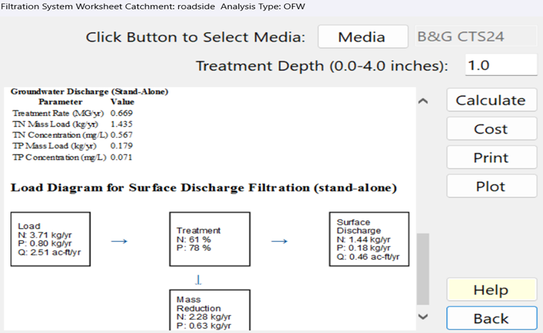
- Load Diagram — the load into the filter (N, P in kg/yr and flow in ac-ft/yr), the treatment (%), the surface discharge and the mass reduction.
Buttons and features
| Button | What it does |
|---|---|
| Calculate / Report / Equations | While an input has changed since the report was shown, the button reads Calculate: it calculates and shows the report. Once the report is current, the button switches the pane between the Equations page (the equations, notes and current values below) and the Report. |
| Cost | Opens the life-cycle cost analysis for this filter (see Cost Analysis). |
| Opens the report in the Report Viewer, where it can be printed or saved. | |
| Plot | Plots the filtration (retention) system efficiency against treatment depth for this catchment, with a marker at the current Treatment Depth. |
| Sizing | Opens Surface Discharge Filter Sizing for this catchment (below). Apply there writes the sized Treatment Depth and media back to this form; Cancel leaves them as they were. |
| Help | Opens this page. |
| Back | Saves the entries, recalculates the filter and returns. |
How BMPFast calculates the filter
Methodology. The filter reads its Hydraulic Capture from the retention curves (Retention Methodology); Retention BMPs explains how that differs from a retention BMP.
Media and Filtration Methodology explains the filter, its sizing and where 18.85 comes from, with a worked example.
Hydraulic Capture (%) = retention efficiency table lookup of Treatment Depth
                        (with the Non-DCIA Curve Number, DCIA % and rainfall zone)
Filter N removal (%)  = Hydraulic Capture x Media N reduction / 100
Filter P removal (%)  = Hydraulic Capture x Media P reduction / 100
Volume Filtered (MG/yr) = Runoff Volume (ac-ft/yr) x 0.3258724 x Hydraulic Capture / 100
N load in the filtered water (kg/yr) = N load in x Hydraulic Capture / 100 x (100 - Media N reduction) / 100   (P the same)
Concentration in the filtered water (mg/L) = load (kg/yr) / (Volume Filtered x 3.785)
Only the water that passes through the filter receives the media’s reduction. If 80% of the water passes through the filter in a year, the pollutant reduction equals 80% of the media’s maximum. The removal follows the Treatment Depth, not the volume reaching the filter: it assumes the filter has been built at least as large as the minimum surface area for that depth (Sizing finds that area).
Applicant’s Handbook reference
Appendix O, Detention with Engineered Media and Filtration: “Treatment efficiency for Detention Pond with Filtration = (Detention efficiency for Volume of the water Detained in the system) + (Volume of water filtered and not detained * Treatment Efficiency of Media)”; BMPFast uses the second term and gives the filter no detention credit of its own.
Section 2.0 Definitions and Terms, “Detention with filtration”: storage of stormwater with gradual release “through an appropriately-sized engineered media or filter system”.
Appendix O, Dry Retention Systems: BMPFast reads the share of annual runoff that passes the filter from these tables (zone, non-DCIA curve number, DCIA, depth up to 4.00 in); the Handbook does not say how to find the filtered volume, so this use of the tables is BMPFast’s.
Source reference
BMPFast method (Filtration.cs): a Surface Discharge Filter’s capture is read from the dry retention tables at its Treatment Depth and multiplied by the media’s reduction; the tables come from Harper and Baker (2007), but using them for the share of runoff a filter passes is BMPFast’s own step.
The answer to “Is the media design residence time more than 2 hours?” matters for two media: when the answer is No, B&G ECT Mixes and SAT use 25% for both TN and TP instead of their full removal. Residence time is the media depth divided by the treatment rate, for example 24 in ÷ 5 in/hr = 4.8 hours for B&G CTS (0.052 gpm/sf is 5 in/hr).
Source reference
Wanielista, M. and Flint, M. (2014). Up-flow Filtration for Wet Detention Ponds. Florida Stormwater Association Annual Meeting, June 12, 2014: an ECT3 filter removes 45 % on its own but 25 % after a wet detention pond, because the pond has already removed the particulate part; BMPFast uses 25 % for B&G ECT Mixes when the residence time is 2 hours or less.
Ferguson Enterprises (2022). Bold & Gold Biosorption Activated Media (BAM) for Enhanced Pollutant Removal in Florida (brochure) (link): a filter downstream of a wet pond removes “25% of the nitrogen and phosphorus”.
BMPFast method (MediaMix.cs): applying the same 25 % to SAT, and treating a filter fed by a wet pond as under 2 hours (Ron, 2026-10-01), are BMPFast’s own rules.
Other methods: when a retention basin is upstream, see Comparison of Methods for Calculating Retention Followed by a Surface Discharge Filter; for two equal filters, Comparison of Methods for Calculating Filters in Series; for two filters with different media, Comparison of Methods for Filter Media in Series, which also works a third method, Specific Yield / Specific Retention, that BMPFast does not calculate. BMPFast 2 lets you choose either of its two methods (Surface discharge filters in series, on the BMPs in Series or Catchment Routing Entry tab). In BMPFast (v1), choose it on the Catchment Configuration window, for filter catchments routed one into another.
Example
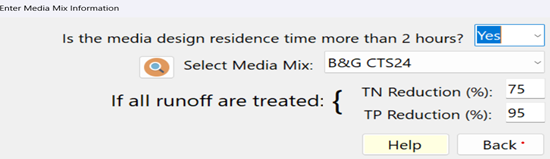
Selecting B&G CTS24 media with a residence time of more than 2 hours gives the media’s full reductions, 75% TN and 95% TP:
An example of using a B&G CTS24 filter in a side drain after a wet pond, with a treatment depth of 1 inch, shows approximately 82% of the annual runoff passing through the filter. The average annual removal is 0.82 × 75 ≈ 61% for TN and 0.82 × 95 ≈ 78% for TP.
Surface Discharge Filter Sizing
The window is described step by step on Sizing.
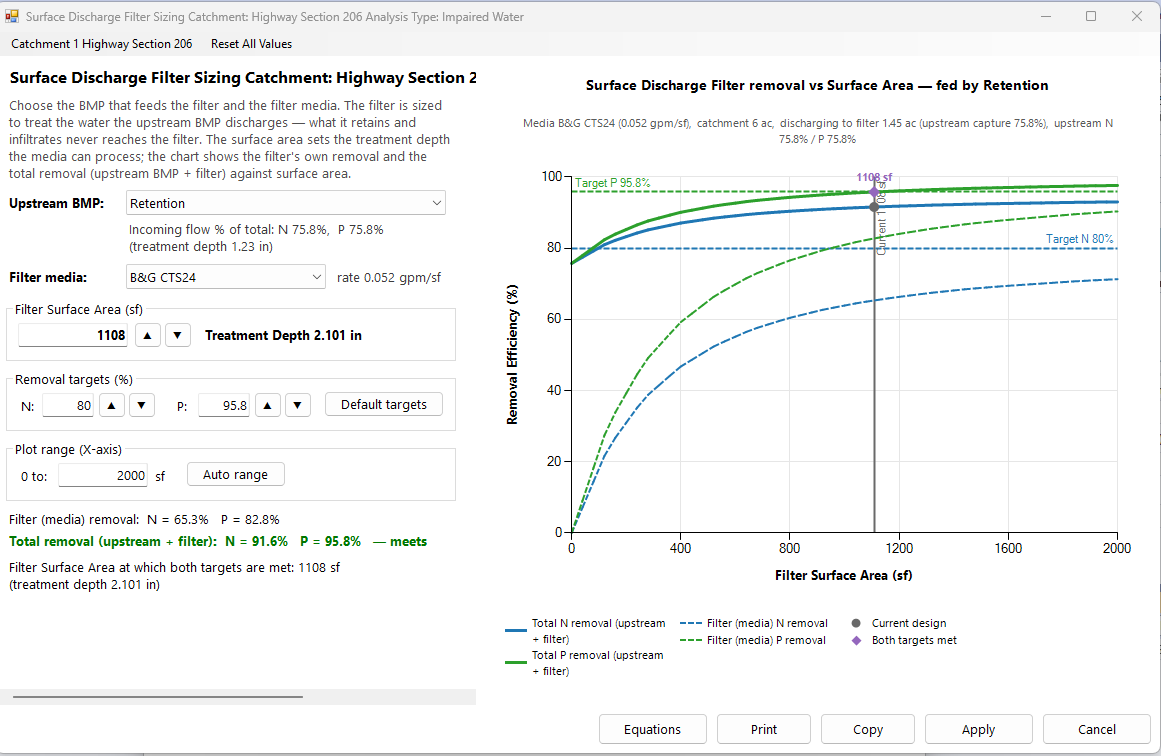
A filter is sized against the BMP that feeds it. Open Surface Discharge Filter Sizing with the Sizing button on this worksheet, or from Tools (Calculators) with Surface Discharge Filter Sizing. Choose the upstream BMP and the filter media; the form finds the smallest filter surface area at which the total removal (upstream BMP plus filter) meets the N and P targets, and plots removal against surface area.
Inputs
| Input | Units | What it means / how it is used |
|---|---|---|
| Upstream BMP | — | The BMP whose discharge the filter treats. The list holds None (catchment runoff to filter) and every BMP on the catchment that has values entered and is a retention-type BMP or a wet detention (not the filter itself, a Multiple BMP or No Treatment). The upstream BMP is used exactly as designed and is not changed. Below the box: the upstream removal (“Incoming flow % of total: N …%, P …%”) with its basis (treatment depth or residence time), and how much it captures and how much area discharges to the filter. With None: the catchment’s runoff (ac-ft/yr) and N and P loads (kg/yr), all of which reach the filter. The form opens on the upstream BMP the filter was last sized with, otherwise on the first BMP in the list. |
| Filter media | — | The media mix; it sets the treatment rate shown beside it (gpm/sf, safety factor included). Choosing User Defined opens the Media Mixes library. The form opens on the filter’s own media. |
| Filter Surface Area (sf) | sf | The design variable. Type an area (Enter or leaving the box applies it) or step it with ▲ ▼ (the step is a round number near 1/20 of the target-meeting area, at least 10 sf). The treatment depth this area can process is shown beside it. The box starts at the area that meets both targets and follows it as the upstream BMP, media or targets change, until you type or step an area of your own; choosing a different upstream BMP or media starts following again. A filter that was sized and applied here opens on its applied area. When no area can meet the targets the box is blank and disabled. |
| Removal targets (%) N, P | % | The total removals the system must reach, 0–100 (▲ ▼ step by 5). Default targets sets them to the project’s Maximum % Removal targets, or, when those are not set, to the filter’s required treatment efficiencies. |
| Plot range (X-axis) 0 to | sf | The largest area on the chart. It is set automatically (at least twice the current area, 1.3 times the target-meeting area, and 200 sf); typing a value fixes it, and Auto range returns to automatic. |
Results
- Treatment Depth (in) — the depth the entered area can process.
- Filter (media) removal N and P (%) — the filter’s own removal at that depth.
- Total removal (upstream + filter) N and P (%) — green with “meets both targets”, red with “below target”.
- Filter Surface Area at which both targets are met (sf), with its treatment depth.
- The chart: total N and P removal (solid lines) and the filter’s own N and P removal (dashed) against surface area, the target lines, the current area and the point where both targets are met. Its subtitle lists the media and rate, the catchment area, the area discharging to the filter, the upstream capture and the upstream removals.
Buttons
| Button | What it does |
|---|---|
| Equations | Opens the Equations page in the Report Viewer: the sizing equations and notes, the current values (upstream BMP, catchment runoff and loads, treatment rate, media reductions, contributing area, upstream capture, area discharging to the filter, curve number, DCIA, rainfall zone, minimum surface area, treatment depth, hydraulic capture, filter and total removals) and the upstream BMP’s own sizing equations. |
| Prints the chart. | |
| Copy | Copies the chart to the clipboard as a picture. |
| Apply | Writes the treatment depth and media to the catchment’s filter, records the surface area (and the upstream BMP and media it was sized with) for the filter’s report, and returns. Disabled while sizing cannot run or the targets cannot be met. |
| Cancel | Returns and restores the filter as it was. |
| Catchment menu / Reset All Values | Switches catchment (leaving a catchment without Apply discards its sizing). Reset All Values goes back to the values the form opened with. |
Sizing equations
Area Discharging to Filter (ac) = Contributing Area (ac) x (100 - Upstream Hydraulic Capture (%)) / 100
Treatment Depth (in) = Filter Surface Area (sf) x Rate (gpm/sf) / (18.85 x Area Discharging to Filter (ac))
18.85 = (43,560 sf/ac / 12 in/ft) / (0.0022288 cfs/gpm x 86,400 s/day): the depth of runoff, over the area discharging to the filter, that the media passes in one day
    equivalently  Minimum Filter Surface Area (sf) = Area Discharging to Filter (ac) x Treatment Depth (in) x 18.85 / Rate (gpm/sf)
Capture (%) = retention efficiency table lookup of Treatment Depth
Filter N removal (%) = Capture x Media N reduction / 100
Filter P removal (%) = Capture x Media P reduction / 100
Total N removal (%) = Upstream N + Filter N x (100 - Upstream N) / 100
Total P removal (%) = Upstream P + Filter P x (100 - Upstream P) / 100- Rate is the media’s treatment rate in gpm/sf and includes the safety factor.
- The 18.85 constant is (43,560 sf/ac ÷ 12 in/ft) divided by (0.0022288 cfs/gpm × 86,400 s/day): the filter passes the whole treatment volume in one day.
- Hydraulic Capture is the water the upstream BMP retains and infiltrates. It leaves the surface-water system and never reaches the filter. A retention-type BMP discharges (100 − Hydraulic Capture)% of the catchment runoff; a wet detention removes no volume and discharges all of it. The filter is sized against the discharged volume, not the raw catchment area.
- The area is the minimum filter surface area for that treatment depth; a larger area is always acceptable. The treatment efficiency assumes the built filter meets that minimum. There is no calculation for partial treatment by an undersized filter.
- With no upstream BMP (None) the catchment’s runoff goes directly to the filter: Upstream Hydraulic Capture and Upstream N/P are 0, the Area Discharging to Filter is the whole catchment area, and the total removal is the filter’s own.
- An upstream retention BMP’s removal comes from its Treatment Depth; an upstream wet detention’s from its residence time. With a wet detention upstream, the filter is treated as having a residence time under 2 hours, so B&G ECT Mixes and SAT use 25%.
Applicant’s Handbook reference
Section 9.5.1 Treatment Train Nutrient Reduction (Equation 9-5): removals in series are combined as 1 − [(1 − Eff1) × (1 − Eff2) × …], and where an upstream BMP changes what reaches the next one “the designer should consider the use of another methodology”; BMPFast combines the upstream BMP and the filter this way and sizes the filter on the volume the upstream BMP discharges.
Source reference
BMPFast method (Surface Discharge Filter Sizing, frmFilterSizing; upstream wet pond treated as under 2 hours, Ron, 2026-10-01): 18.85 is a unit conversion (one inch over one acre, 3,630 cf, divided by one day at 1 gpm, 192.57 cf); the area found is the minimum for that Treatment Depth, and there is no credit for an undersized filter.
Messages
- “The catchment has no post-development area.” / “Select the filter media.” / “The selected media has no treatment rate (gpm/sf).” / “The upstream BMP retains and infiltrates all of the runoff — nothing discharges to the filter.” — sizing cannot run until this is fixed; Apply is disabled.
- “Filter Surface Area cannot meet treatment requirements.” — even a 4 in treatment depth (the end of the retention tables) does not reach both targets. Choose a different media or upstream BMP, or lower the targets. The curves stay on the chart so you can see how far short the removal falls.
- “Enter a surface area in square feet.”, “Targets must be numbers between 0 and 100.”, “Plot range must be a positive number.” — the value typed was not accepted.
Comparison of methods
Where a Surface Discharge Filter follows another filter or a retention basin, there is more than one way to calculate it. Each page below works one problem by each method and shows how far apart they are; each says which method BMPFast uses. Every number on them is from BMPFast or its retention curves.
- Comparison of Methods for Calculating Filters in Series — Surface Discharge Filters one after another, worked on two equal filters: the Handbook equation (Equation 9-5) or the Equivalent Treatment Depth (one system).
- Comparison of Methods for Filter Media in Series — two filters with different media, one after another: the Handbook equation and the Equivalent Treatment Depth, which BMPFast calculates, beside a third, Specific Yield / Specific Retention, which it does not (worked on the page from BMPFast’s retention curve, for a range of Specific Yield to Specific Retention ratios).
- Comparison of Methods for Calculating Retention Followed by a Surface Discharge Filter — a retention basin followed by a filter: Equation 9-5 (what BMPFast uses) or the two as one storage, over a range of filter sizes.
Sample problems
Worked problems solved in BMPFast, each with every input, the steps with screen captures, the program’s results, a hand check and the project file to download. Captures are for demonstration only. All of them: BMPFast sample problems.
- Surface discharge filter with B&G CTS12
- Surface discharge filter with B&G CTS24 for an impaired water
- Sizing a filter after a retention basin
- Sizing a filter after a wet pond
- Service life of a B&G CTS24 filter
- Filter area for a 20-year service life
- Media mix: a filter with and without media
Related pages
- Media Mix — the media dialog, the built-in mixes and your own mixes, BAM background and FAQ.
- Media Filter Service Life — how many years the media can keep removing phosphorus.
- Cost Analysis.
- ICS media removal, August 2023 (PDF) — Dr. Wanielista’s memo on the ICS (Iron, Clay and Sand) media: its mix, laboratory removals and design treatment rate; summarized on the Media Mix page.